91
Ultron NT Series
7XUQRQHDFKH[WHUQDOEDWWHU\FDELQHW¶VBattery breaker.
4. Press the ‘ON¶DQGµ
¶EXWWRQVVLPXOWDQHRXVO\IRUVHFRQGV$IWHUWKDWWKH
inverter will start up. Once the inverter voltage is established, the power will be
switched from bypass to inverter. At this moment, it will be the inverter to supply
power to the connected loads, and the LCD will display ‘Normal Mode¶$IWHU
30 seconds, the UPS will automatically execute a battery test to check if the
connected batteries are normal or not.
5. About 40 seconds after the UPS turns on normally, it will be the bypass to supply
power to the connected loads, and the LCD will display ‘Bypass Mode ECO
,IWKHEDWWHU\WHVWLVQRUPDOXVHDYROWDJHPHWHUWRPHDVXUHWKH836¶VRXWSXW
voltage (per phase). If normal, turn on the UPS Output switch.
7.2.5 Normal Mode Start-up Procedures (Parallel)
NOTE :
Before executing the following start-up procedures, please refer to 7.1
3UH6WDUWXS3UH7XUQR௺:DUQLQJV¿UVW
%HIRUHSDUDOOHOLQJ836VSOHDVHFRQ¿UPWKDWHDFKXQLW¶VFDSDFLW\YROWDJHDQG
IUHTXHQF\DUHWKHVDPH
7XUQRQHDFK836¶VReserve Input breaker or switch, and each LCD will display
‘Bypass Mode
3. Use the provided parallel cables to connect the parallel UPSs (at maximum 8
XQLWVDQGPDNHVXUHWKDWHDFKSDUDOOHOFDEOHLV¿UPO\¿[HG
4. Use the RS-232 and UPS parameter setting software (please contact service
SHUVRQQHOWRVHWXSHDFKSDUDOOHO836¶VSDUDOOHO,'1R7KHSDUDOOHO,'1RLV
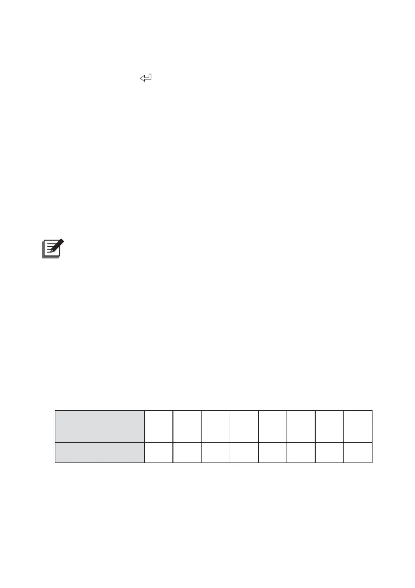
GLႇHUHQWIURPWKH,'1RVKRZQRQWKH/&'3OHDVHUHIHUWRWKHWDEOHEHORZIRU
the parallel ID No.
UPS
(At Max. 8 Units)
1
st
2
nd
3
rd
4
th
5
th
6
th
7
th
8
th
Parallel ID No. 12 23 34 45 56 67 78 81
7XUQRQHDFK836¶VRectifier Input breaker or switch and wait about 30
seconds. After that, the DC BUS voltage will be established.
7XUQRQHDFKH[WHUQDOEDWWHU\FDELQHW¶VBattery breaker.
 Loading...