67
Ultron NT Series
Chapter 6 : UPS Display and Settings
6.1 Control Panel
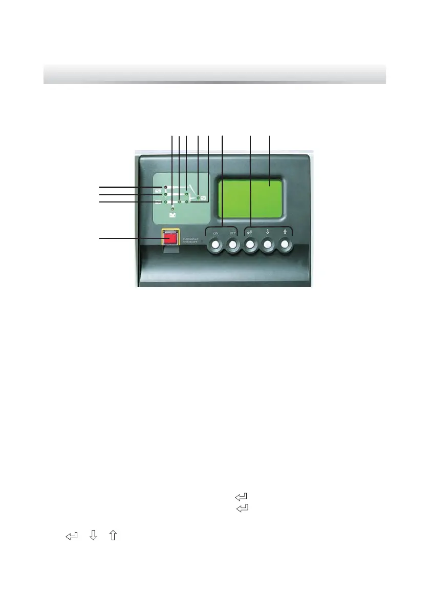
Figure 6-1: Control Panel
4
3
2
1
5 7 8 9 10 11 12
6
1. EPO switch: When an emergency event occurs, press the EPO switch to turn
RႇWKHUHFWL¿HULQYHUWHUDQGRXWSXWRIWKH836
5HFWL¿HU/('JUHHQ:KHQWKHUHFWL¿HUZRUNVQRUPDOO\
3. Reserve power LED (green): When the reserve source is normal.
4. Maintenance bypass power LED (red): When the manual bypass breaker or
switch is turned on.
5. Battery LED (orange): When the mains source is abnormal and the loads are
supplied by battery power.
6. Inverter LED (green): When the inverter works normally.
7. Reserve power static switch LED (green): When the loads are supplied by the
reserve AC power.
8. AC output LED (green): When the UPS has normal output.
9. Inverter M.C. LED (green): When the loads are supplied by the inverter.
10. Inverter control buttons: Press “ON” and “
” simultaneously for 3 seconds to
turn on the inverter and press “OFF” and “
” simultaneously for 3 seconds to
WXUQRႇWKHLQYHUWHU
11. “
” “ ” “ ” buttons: Control the LCD display and set up parameters.
12. LCD display.
 Loading...