Chapter 7 UPS Operation
92
3UHVVRQHRIWKHSDUDOOHO836V¶µON¶DQGµ ¶EXWWRQVVLPXOWDQHRXVO\IRU
seconds, and its inverter will start up. Once the inverter voltage is established,
the LCD will display ‘Bypass Mode
8. Repeat the above-mentioned Step 7 to the rest of the parallel UPSs. After the
ODVWSDUDOOHO836¶VLQYHUWHUYROWDJHLVHVWDEOLVKHGHDFKSDUDOOHO836¶VFRQWDFWRU
will activate and each LCD will display ‘Normal Mode
8VHDYROWDJHPHWHUWRPHDVXUHHDFKSDUDOOHO836¶VRXWSXWYROWDJHSHUSKDVH
The output voltage difference must be lower than 5V. If normal, turn on each
XQLW¶VUPS Output breaker or switch.
1RZWKHWRWDOORDGVZLOOEHHTXDOO\VKDUHGE\WKHSDUDOOHO836V
7.2.6 Battery Mode Start-up Procedures (Parallel)
NOTE :
1. Before executing the following start-up procedures, please refer to 7.1
3UH6WDUWXS3UH7XUQR௺:DUQLQJV¿UVW
2. Battery start function is customized and only applicable to the model that
has the built-in battery contactor.
%HIRUHSDUDOOHOLQJ836VSOHDVHFRQ¿UPWKDWHDFKXQLW¶VFDSDFLW\YROWDJHDQG
IUHTXHQF\DUHWKHVDPH
7XUQRQHDFKH[WHUQDOEDWWHU\FDELQHW¶VBattery breaker.
3UHVVHDFKSDUDOOHO836¶VEDWWHU\VWDUWXSVZLWFKRQFH
4. Use the provided parallel cables to connect the parallel UPSs (at maximum 8
XQLWVDQGPDNHVXUHWKDWHDFKSDUDOOHOFDEOHLV¿UPO\¿[HG
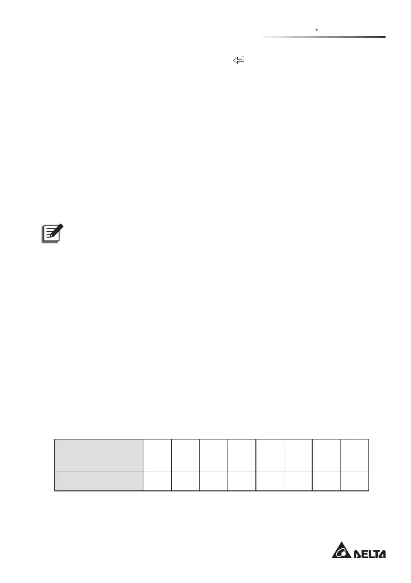
5. Use the RS-232 and UPS parameter setting software (please contact service
SHUVRQQHOWRVHWXSHDFKSDUDOOHO836¶VSDUDOOHO,'1R7KHSDUDOOHO,'1RLV
GLႇHUHQWIURPWKH,'1RVKRZQRQWKH/&'3OHDVHUHIHUWRWKHWDEOHEHORZIRU
the parallel ID No.
UPS
(At Max. 8 Units)
1
st
2
nd
3
rd
4
th
5
th
6
th
7
th
8
th
Parallel ID No. 12 23 34 45 56 67 78 81
$IWHUHDFK836¶V'&%86YROWDJHUHDFKHVDURXQG9HDFK836¶VEDWWHU\
contactor will start up.
 Loading...