69
Ultron NT Series
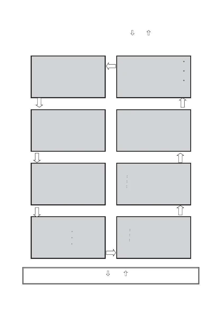
After entering the “Measure Page”, press the “
” or “ ” button to monitor the
present status and parameters of the UPS.
The display order is as follows:
Rectifier Input
Voltage Current
U V : 3 8 0 V 6 . 8 A
V W : 3 8 0 V 8 . 2 A
W U : 3 8 0 V 8 . 2 A
Rectifier
: 5 9 . 9Hz
Frequency
Bypass Input
Voltage
R : 2 1 7 . 4 V 3 7 7 V
S : 2 1 8 . 6 V 3 7 8 V
T : 2 1 8 . 3 V 3 7 7 V
Bypass
: 5 9 . 9Hz
Frequency
Inverter Output
Voltage
R : 2 2 0 . 3 V 3 8 1 V
S : 2 1 9 . 9 V 3 8 0 V
T : 2 2 0 . 0 V 3 8 1 V
Inverter
: 5 9 . 9Hz
Frequency
UPS Output
Voltage
R : 2 2 0. 2 V Ǵ
3 8 1 V
S : 2 2 0. 2 V Ǵ
3 8 1 V
T : 2 2 0. 2 V Ǵ
3 8 1 V
UPS Output
: 5 9 . 9Hz
Frequency
Rectifier
:
2 7
Temperature
Inverter
:
2 8
Temperature
UPS
:
2 8
Temperature
Transformer
: Normal
Temperature
Battery
: 3 9 3 V
Voltage
Battery
: 3 A
Current
Battery
:
Boost
Status charge
Battery
: 8 6 %
Capacity
UPS Output
Loading
R Ǻ
0. . 0 Kva 0. . 0 Kw
S Ǻ
0. . 0 Kva 0. . 0 Kw
T Ǻ
0. . 0 Kva 0. . 0 Kw
R : Power Factor 0. 0 0
UPS Output
Loading
R Ǻ
0 % 0.0 A
S Ǻ
0 % 0.0 A
T Ǻ
0 % 0.0 A
UPS Output
: 5 9 . 9Hz
Frequency
C
C
C
To leave the “Measure Page”, press the “ ” and “ ” buttons simultaneously to return to
the “Main Menu”.
 Loading...