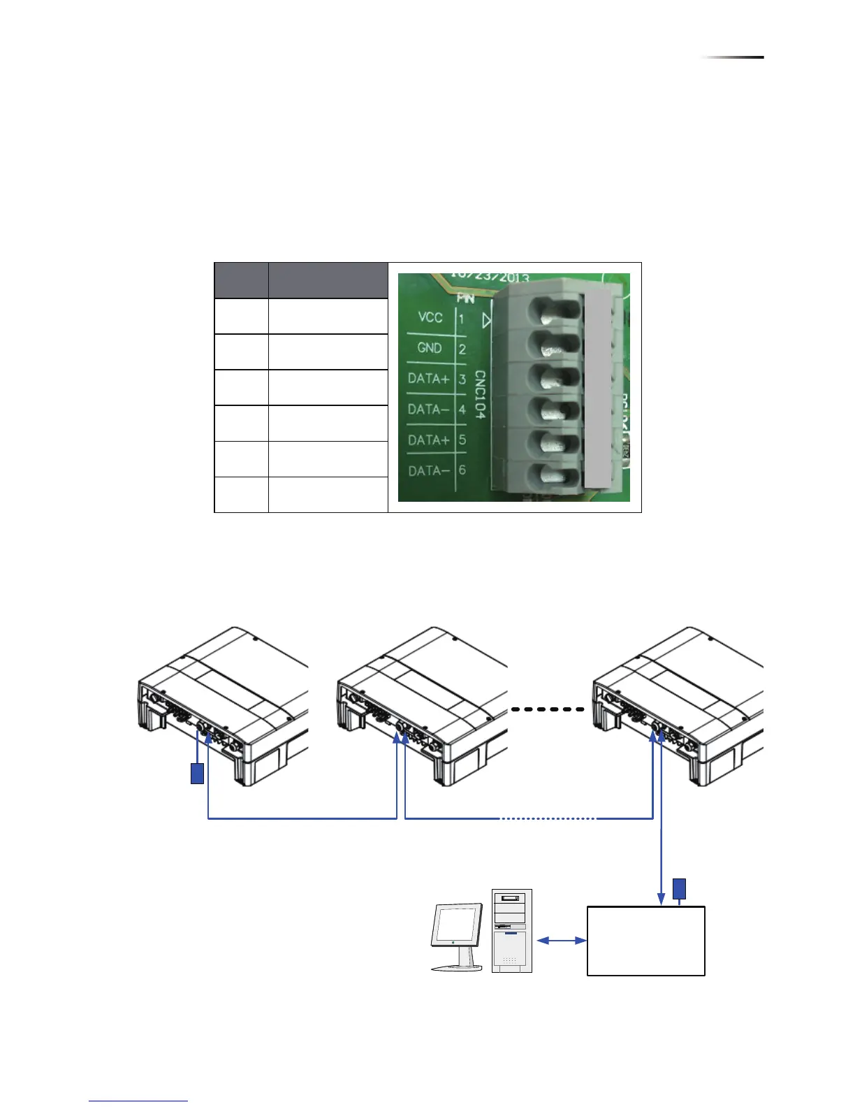
4.4.3. RS-485 Connection
The pin definition of RS-485 is shown in Table 4-5. Installers should switch
ON the terminal resistor when single inverter is installed. The wiring of
multi-inverters connection is shown as Figure 4-8. Installers should switch
ON terminal resister at the first and last devices of the RS-485 chain as
shown. Other terminal resisters should be switched OFF.
Pin Function
1 VCC (+12V)
2 GND
3 DATA+
4 DATA-
5 DATA+
6 DATA-
RPI M6A/ M8A/ M10A
Table 4-5 Definition of RS 485 pin
Figure 4-8 Multi-inverter connection illustration
 Loading...