EasyManuals Logo
Home>Delta>DC Drives>VFD1A5MS43ANSAA

Delta VFD1A5MS43ANSAA User Manual

Delta VFD1A5MS43ANSAA
805 pages
To Next Page IconTo Next Page
To Previous Page IconTo Previous Page
Page #406 background imageLoading...
Page #406 background image
Chapter 12 Descriptions of Parameter SettingsMS300
397
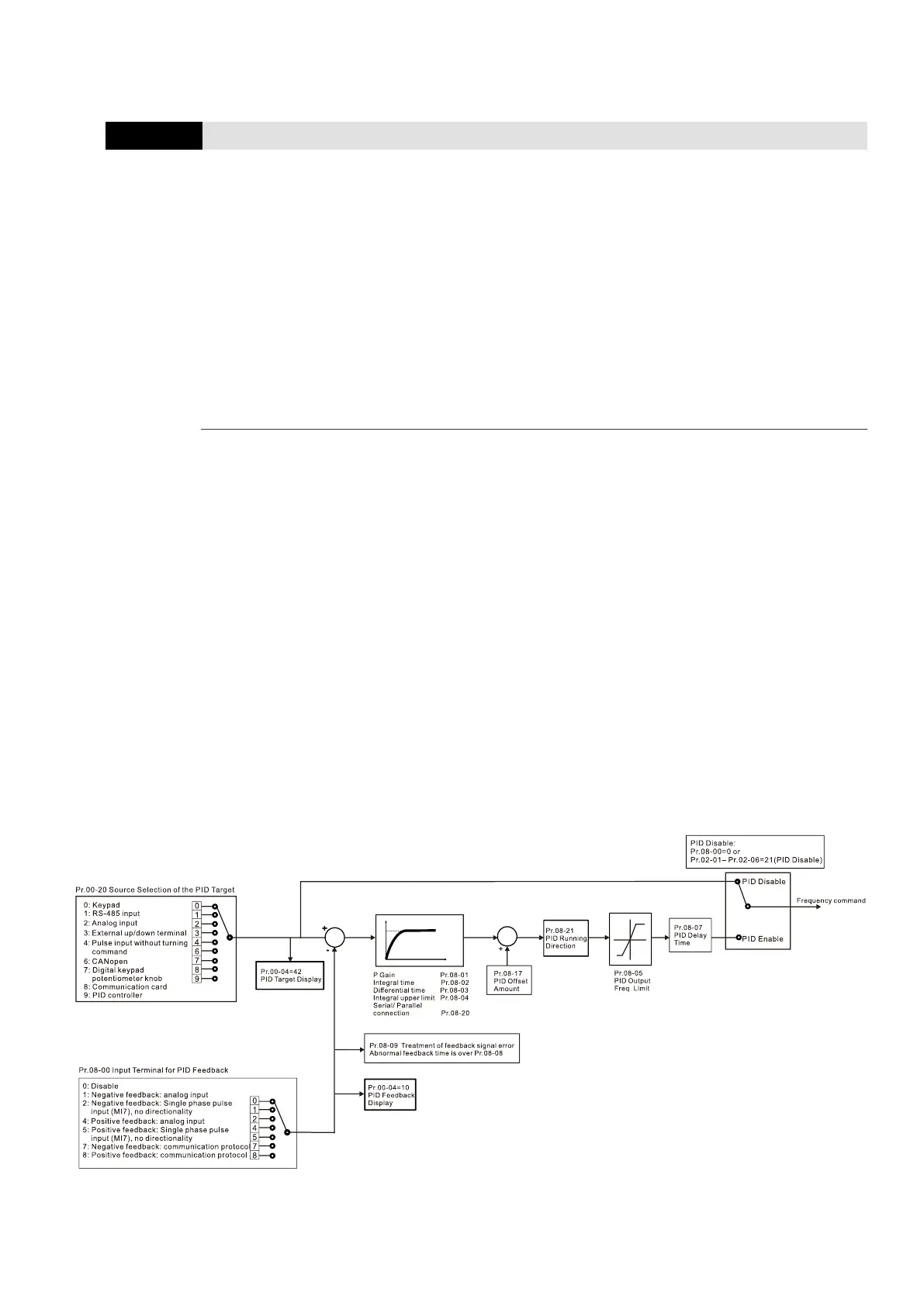
08 High-function PID Parameters
You can set this parameter during operation.
08-00
Terminal Selection of PID Feedback
Default: 0
Settings
0: No function
1: Negative PID feedback: by analog input (Pr.03-00, 03-01)
2: Negative PID feedback: by single-phase input (MI7), without direction
(Pr.10-16 = 5)
4: Positive PID feedback: by analog input (Pr.03-00, 03-01)
5: Positive PID feedback: by single-phase input (MI7), without direction
(Pr.10-16 = 5)
7: Negative PID feedback: by communication protocols
8: Positive PID feedback: by communication protocols
Negative feedback:
Error = + Target value (set point) – Feedback. Use negative feedback when the detection value
increases if the output frequency increases.
Positive feedback:
Error = - Target value (set point) + Feedback. Use positive feedback when the detection value
decreases if the output frequency increases.
When Pr.08-00 ≠ 7 or ≠ 8, the input value is disabled. The setting value does not remain when
the drive is powered off.
The related applicable parameters to set Pr.08-00 include:
Pr.00-20 Master frequency command source (AUTO)
Pr.03-0003-01
When Pr.00-20 = 2, set Pr.03-0003-01 = 4 (PID target value)
When Pr.08-00 = 1 or 4, set Pr.03-0003-01 = 5 (PID feedback signal)
Refer to the following description of details.

Table of Contents

Questions and Answers:

Question and Answer IconNeed help?

Do you have a question about the Delta VFD1A5MS43ANSAA and is the answer not in the manual?

Delta VFD1A5MS43ANSAA Specifications

General IconGeneral
BrandDelta
ModelVFD1A5MS43ANSAA
CategoryDC Drives
LanguageEnglish

Related product manuals