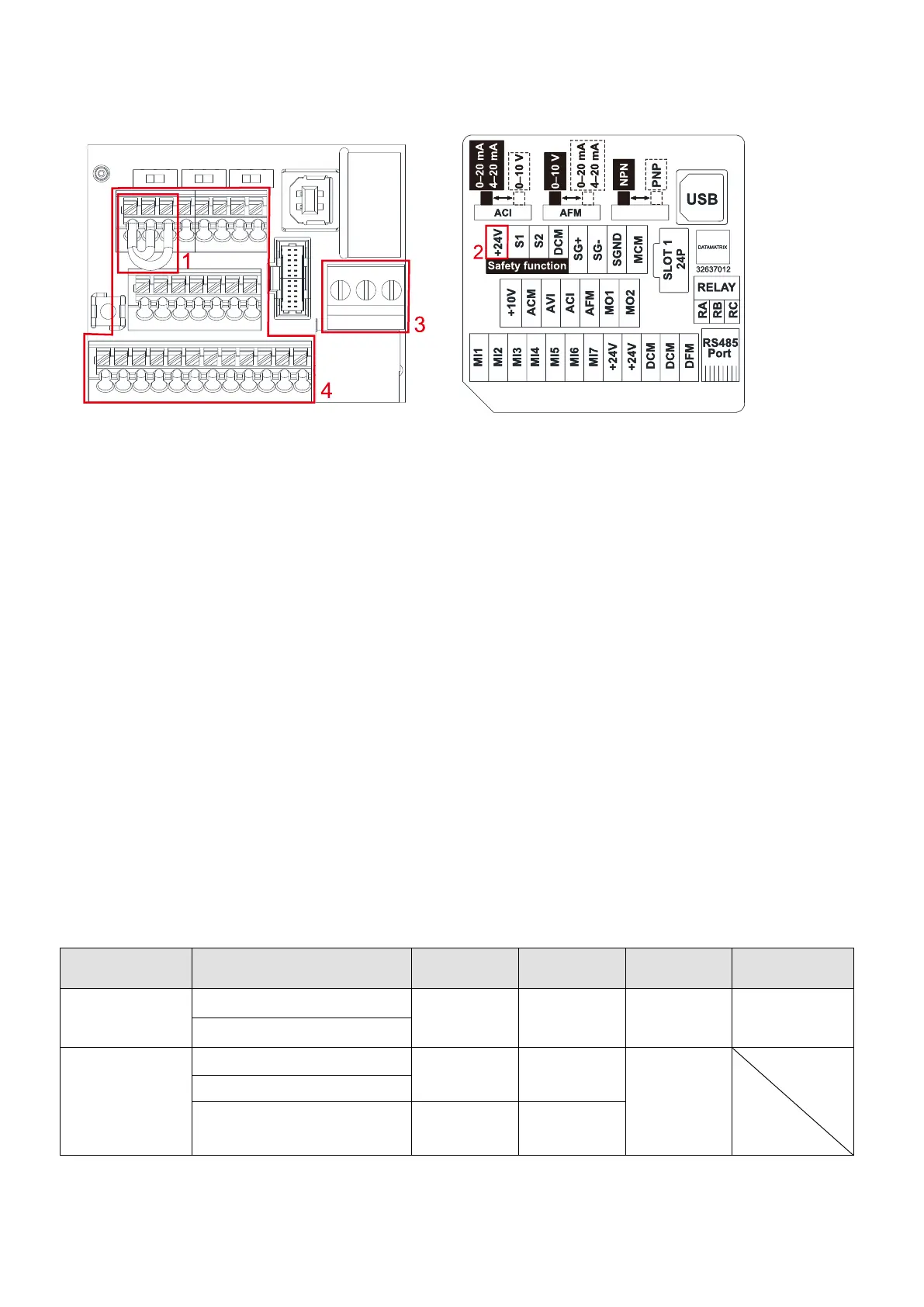
Wiring precautions:
1. The factory default is +24 V
DC
/ S1 / S2 short-circuited by jumper, as shown in Area 1 in Figure 6-6.
Refer to Figure 4-2 in Chapter 4 WIRING for details.
2. Use the +24 V
DC
power supply of the safety function (as shown in Area 2 in Figure 6-7) for STO
only. Do NOT use it for other purposes.
3. The RELAY terminal uses the PCB terminal block (as shown in Area 3 in Figure 6-6):
Tighten the wiring with a 2.5 mm (wide) × 0.4 mm (thick) slotted screwdriver.
The ideal length of stripped wire at the connection side is 9–10 mm.
When wiring bare wires, ensure that they are perfectly arranged to go through the wiring holes.
4. The Control terminal uses the push-in spring terminal block (as shown in Area 4 in Figure 6-6):
When removing wires, use the slotted screwdriver to press down the terminal, and the
suggested force is 1.5 kgf.
Tighten the wiring with a 2.5 mm (wide) × 0.4 mm (thick) slotted screwdriver.
The ideal length of stripped wire at the connection side is 9 mm.
When wiring bare wires, ensure that they are perfectly arranged to go through the wiring holes.
Wiring Specifications of Control Terminal
 Loading...