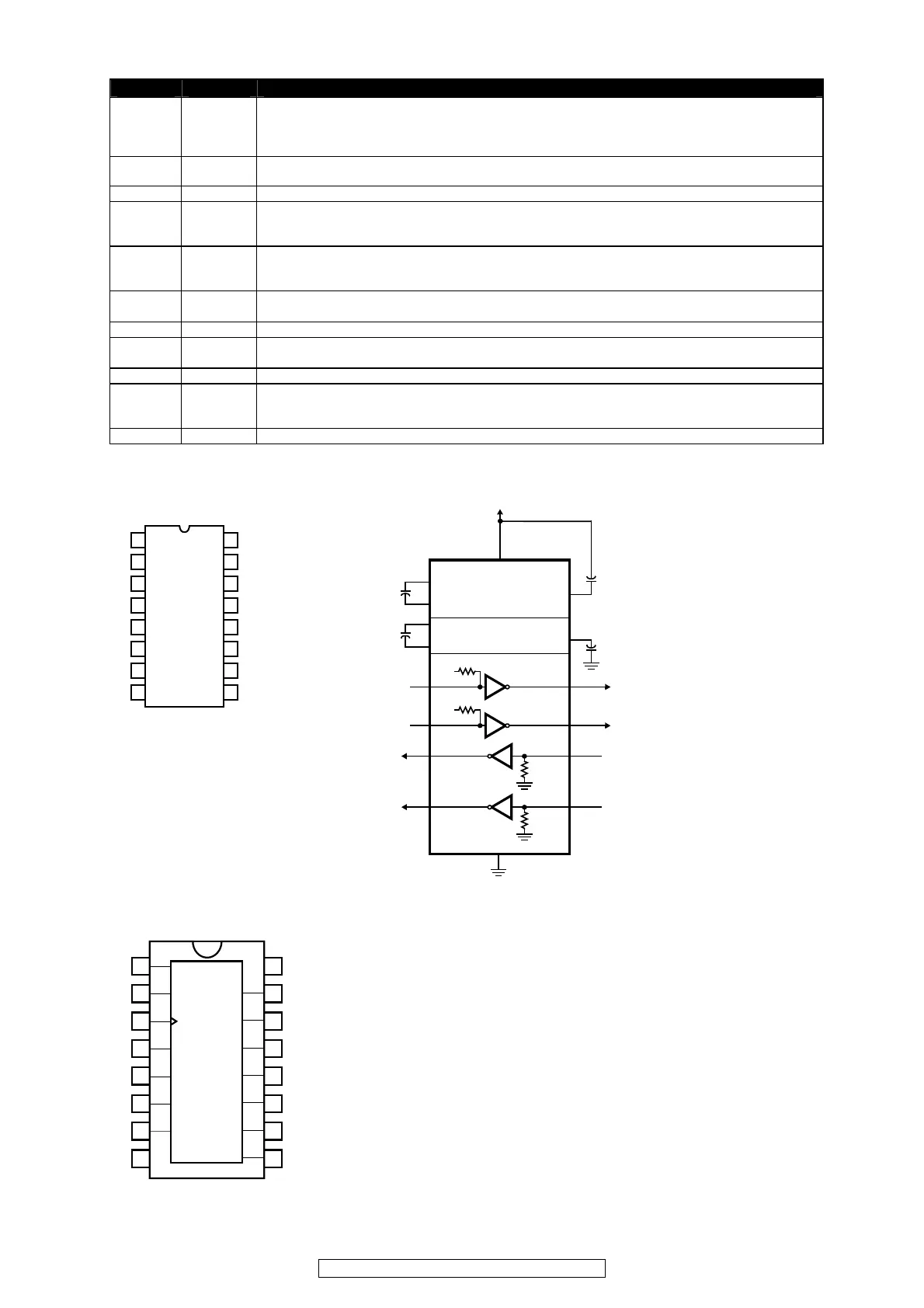
PIN NAME FUNCTION
1, 21-24 NC(SW)
No Connect. These pins are internally connected to the common drain output of the internal
MOSFETs. NC(SW) pins are not to be electrically connected to any external signal, ground, or
voltage. However, they must be soldered to the PCB. Failure to follow this guideline may result
in part malfunction or damage.
2-3, 8-9 PGND
Input/Output Power Ground. Connect these pins to the ground electrode of the input and
output filter capacitors. Refer to Layout Considerations section for details.
4-7 VOUT Voltage and Power Output. Connect these pins to output capacitor(s).
10-12 VS2-0
Output Voltage Select. These pins set one of seven preset output voltages and the external
divider option (refer to Electrical Characteristics table for more details), and can be directly
pulled up to V
IN
or pulled down to GND; these pins must not be left floating.
13 VSENSE
Sense Pin for Internally Programmed Output Voltages with VID Codes. For either VID code or
external resistor divider applications, connect this pin to the last local output filter capacitor for
internal compensation.
14 VFB
Feedback Pin for External Voltage Divider Network. Connect a resistor divider to this pin to set
the output voltage. Use 340 k:, 1% or better for the upper resistor.
15 AGND Analog Ground for the Controller Circuits
16 AVIN
Analog Voltage Input for the Controller Circuits. Connect this pin to the input power supply.
Use a 1 PF bypass capacitor on this pin.
17 POK Power OK with an Open Drain Output. Refer to Power OK section.
18 ENABLE
Input Enable. A logic high signal on this pin enables the output and initiates a soft start. A
logic low signal disables the output and discharges the output to GND. This pin must not be
left floating.
19-20 PVIN Input Power Supply. Connect to input supply. Decouple with input capacitor(s) to PGND.
 Loading...