Control Cavity 9–5
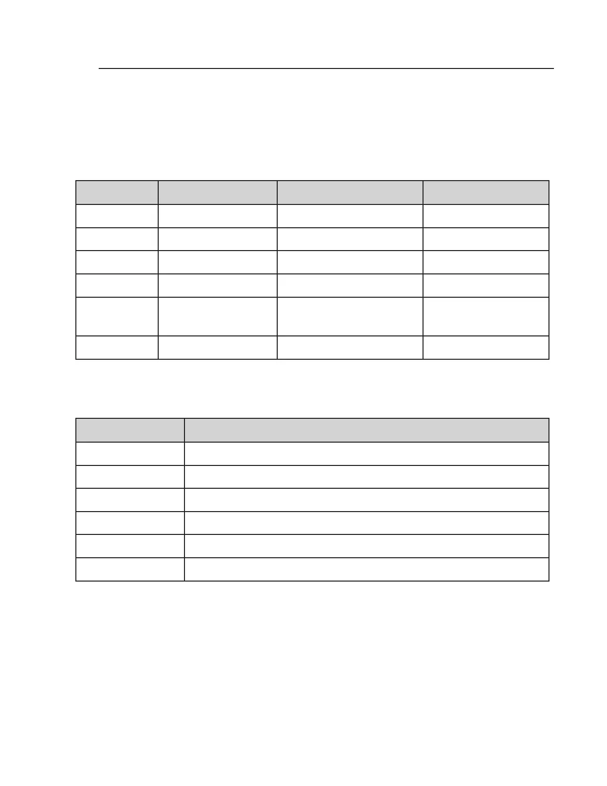
Meter Setting Wire Combination Good Motor Resistance Bad Motor Resistance
200 Black/Red 1.5 – 2.5 ohms Innity
200 Black/Gray 1.5 – 2.5 ohms Innity
200 Yellow/Blue 1.5 – 2.5 ohms Innity
200 Yellow/Black Innity Any reading
2000K or 2M Ground/All motor leads Innity
Any reading; possibly wa-
ter in motor. Dry windings
and retest.
Megger Ground/All motor leads 500M or higher Below 500M
Motor Field Winding Resistance
Table 9–1
Motor Windings Test
Perform motor winding resistance checks per the following charts to verify motor condition.
Note:
While all of the wires are disconnected between the control bracket and the power cable,
replace the two O-rings on the motor casting before rewiring the controls. Use Molycote 55
grease on the motor housing and the motor head O-rings. Use silicone grease on all other
O-rings.
Wire Color Function
Black Run/Start windings and internal thermal protector
Blue Run windings
Gray Run windings
Yellow Run windings
Red Run windings
Orange Jumper lead (120V only)
Table 9–2
Motor Wire Functions
 Loading...