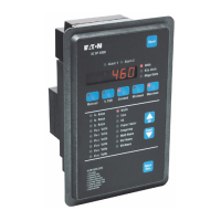
IQ DP-4000
SECTION 5 - PROGRAMMING THE IQ DP-4000 TD 17548B
21
5.1 INTRODUCTION
This section identifies all of the programmable functions
of the IQ DP-4000. The device is programmed by
specifying setpoint values for functions you want
monitored. Setpoints are entered using the Save button
(S1), Setpoint Switches (S2), Rotary Select Switch (S3),
and are displayed via the Setpoint Display LED Bank
(DS30) (see Figure 2.2). Set the Rotary Select Switch
(S3) to 0 when you are finished programming.
You use the Setpoint switches (S2) in conjunction with
the Rotary Select switch (S3) to program setpoint
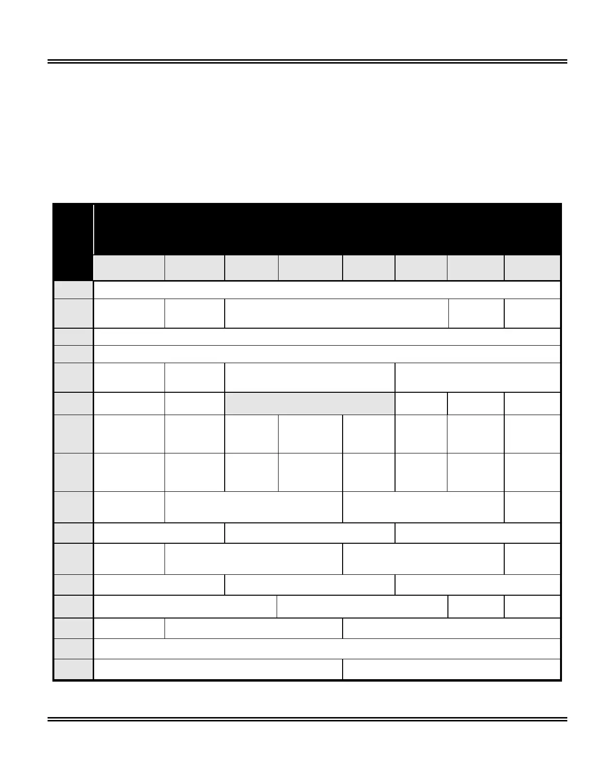
values specific to your needs. Table 5.A, Setpoint
Master Record Sheet, lists all of the possible functions
that may be set. The left column lists the 16 Rotary
Select Switch Positions and the top row lists the
Setpoint Switches. Appendix B contains a blank Master
Setpoint Record Sheet for recording your setpoint
values. Use the details in this section to define your
setpoint values and record the values in the blank
Setpoint Switches (S2)
Pressing & Holding S1 causes all 8 switches on S2 to be saved according to the Rotary Switch S3
Always set all 8 S2 switches. See the pushbutton locations in Figure 2.2 (p.4).
Rotary
Select
Switch
(S3)
S2.1 S2.2 S2.3 S2.4 S2.5 S2.6 S2.7 S2.8
S3.0
Test Position—When you are not programming the unit, turn the Rotary Select Switch to 0.
S3.1
System
Configuration Frequency Nominal AC Line Voltage
Voltage
Transformer
Ratio
Current
Transformer
Primary
S3.2
Voltage Transformer Ratio
S3.3
Current Transformer Primary
S3.4
Phase Sequence
Power
Demand
Fixed/Sliding
Power Demand
Time Interval
Current Demand
Time Interval
S3.5
Reset Energy Energy
Resolution
Not Used Var/Power
Factor Sign
Discrete
Input
Sync Pulse
S3.6
Alarm 1
Relay Mode
Alarm 1
Latch/Unlatch
Alarm 1
Overvoltage
Alarm 1
Undervoltage
Alarm 1
Voltage
Phase Loss
Alarm 1
Voltage
Phase
Unbalance
Alarm 1
Voltage
Phase
Reversal
Alarm 1
Current
Phase Loss
S3.7
Alarm 2
Relay Mode
Alarm 2
Latch/Unlatch
Alarm 2
Overvoltage
Alarm 2
Undervoltage
Alarm 2
Voltage
Phase Loss
Alarm 2
Voltage
Phase
Unbalance
Alarm 2
Voltage
Phase
Reversal
Alarm 2
Current
Phase Loss
S3.8
Alarm 1
Disable/Enable
Alarm 1
Trip Delay
Alarm 1
Reset Delay
Alarm 1
Overvoltage
Detection
S3.9
Alarm 1
Overvoltage Detection
Alarm 1
Undervoltage Detection
Alarm 1
Voltage Phase Unbalance Detection
S3.A
Alarm 2
Disable/Enable
Alarm 2
Trip Delay
Alarm 2
Reset Delay
Alarm 2
Overvoltage
Detection
S3.B
Alarm 2
Overvoltage Detection
Alarm 2
Undervoltage Detection
Alarm 2
Voltage Phase Unbalance Detection
S3.C
Alarm 1
Reset Threshold
Alarm 2
Reset Threshold
PowerNet
Programming
DP-4000 /
DP - 2 Mode
S3.D
Pulse Initiator
Load Shed
Pulse Initiator
Parameter
Load Shed /Restore Load
Range Settings
S3.E
Load Shed /Restore Load
Range
S3.F
Load Shed
Parameter
Pulse Initiator
Rate
Table 5.A Setpoint Master Sheet (The Most Important Page in This Manual)
 Loading...