IQ DP-4000
SECTION 5 - PROGRAMMING THE IQ DP-4000 TD 17548B
24
voltages will not be displayed if the IQ DP-4000 is
configured as a 3-wire system.
Note: When external voltage transformers are used,
the nominal AC line voltage setting indicates the voltage
present on the secondary terminals of the PTs. Also,
L-N voltages will not be displayed if the unit is
configured as a three-wire.
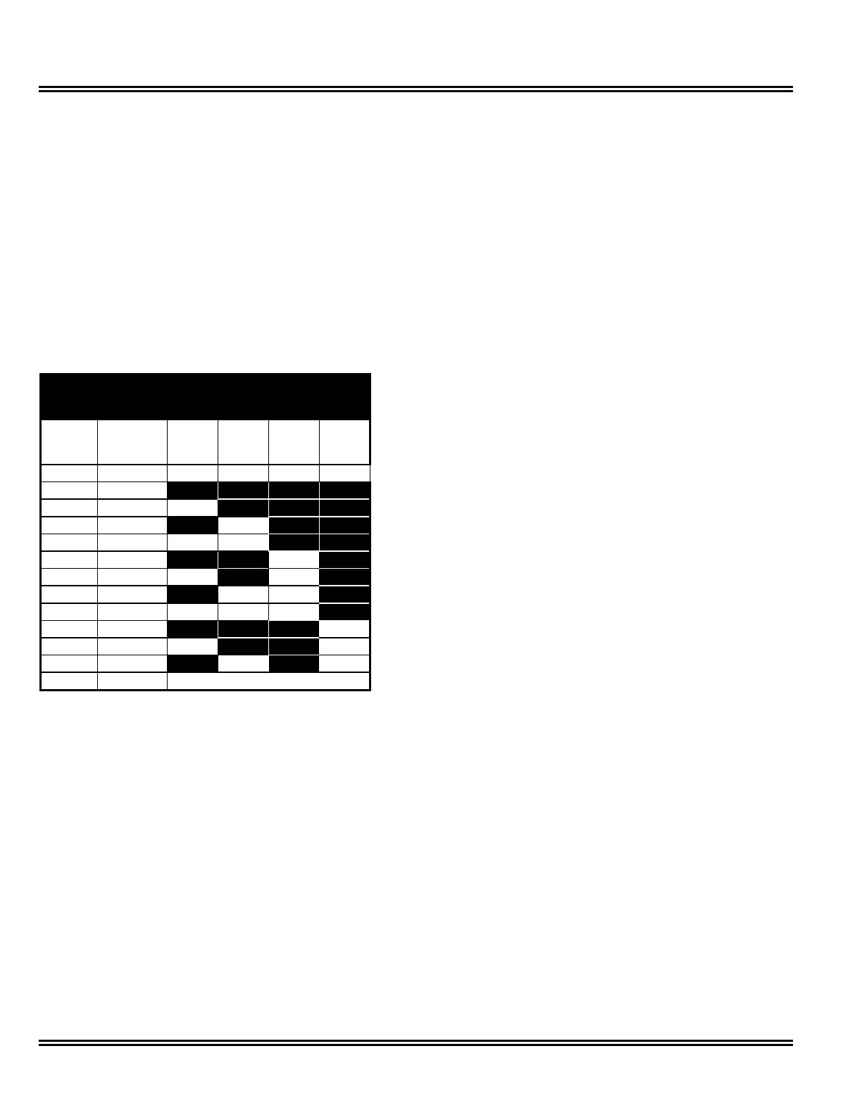
Setpoint Switches S2.(3 to 6) for Rotary Switch position
S3.1 specify the nominal AC line voltage. Record the
desired switch settings according to Table 5.F. Follow
the table’s line-to-line column when the wiring
configuration of the AC line is 3-wire. Use the line-to-
neutral column when the AC line configuration is 4-wire.
= OFF = ON
Voltages
(Nominal)
S3.1 Switch Settings
(Set all 8 S2 switches)
Line-
to-Line
Line-
to-
Neutral
S2.3 S2.4 S2.5 S2.6
100 58 on on on on
110 64 off off off off
120 69 on off off off
208 120 off on off off
220 127 on on off off
240 138 off off on off
380 219 on off on off
416 240 off on on off
460 266 on on on off
480 277 off off off on
575 332 on off off on
600 336 off on off on
600 336 Any other selection
Table 5.F AC Line Voltage
5.6 VOLTAGE TRANSFORMER RATIO SETPOINT
Some systems may include optional, user-provided
potential voltage transformers (this is required above
600V). You must take these ratios into account by using
Setpoint Switches S2.7 for Rotary Switch position S3.1,
and the eight Setpoint Switches S2.(1 to 8) for Rotary
Switch position S3.2. See Appendix A for a listing of the
available PT ratios, and their corresponding settings.
You must set all 8 S2 switches.
5.7 CURRENT TRANSFORMER PRIMARY
SETPOINT
The primary winding of the user-provided external
current transformers can vary from 5 amps to 12,800
amps; the secondary winding is assumed to be 5 amps.
Setpoint Switches S2.8 for Rotary Switch position S3.1,
and the eight switch settings S2.(1 to 8) for Rotary
Switch position S3.3, must correspond to the external
current transformer’s primary rating. See Appendix A for
a listing of the available CT primary ratings, and their
corresponding settings.
5.8 PHASE SEQUENCE SETPOINT
The IQ DP-4000 can be programmed to correspond to
either a nominal ABC or CBA sequence, by a single
Setpoint Switch S2.1 for Rotary Switch position S3.4. A
power system with an ABC sequence has phase A
leading phase B by 120 degrees, and phase B leading
phase C by 120 degrees. A system with a CBA
sequence has phase C leading phase B by 120
degrees, and phase B leading phase A by 120 degrees.
Record the desired setting for S2.1 for Rotary Switch
position S3.4: (You must set all 8 S2 switches)
• OFF position for an ABC sequence
• ON position for a CBA sequence
5.9 DEMAND SETPOINTS
If you set up the IQ DP-4000 to use an internal sync
pulse (see Section 5.15.2 p.34), you must determine
the type of demand, and time interval for the demand
window. The present demand and peak demand are
computed for the following parameters:
• Current Related Parameters. For the current related
parameters, the demand calculation is always
based on a fixed window. Section 5.9.3 describes
programming the current demand times. The
current related parameters are:
- I
A
Amps
- I
B
Amps
- I
C
Amps
• Power Related Parameters. For the power related
parameters, the demand can be based on either a
fixed or sliding window. See Section 5.9.1 for
selecting a fixed or sliding demand window and
Section 5.9.2 for programming the power related
demand times. The power related parameters are:
- Watts
- Vars
- VA
 Loading...