IQ DP-4000
SECTION 5 - PROGRAMMING THE IQ DP-4000 TD 17548B
30
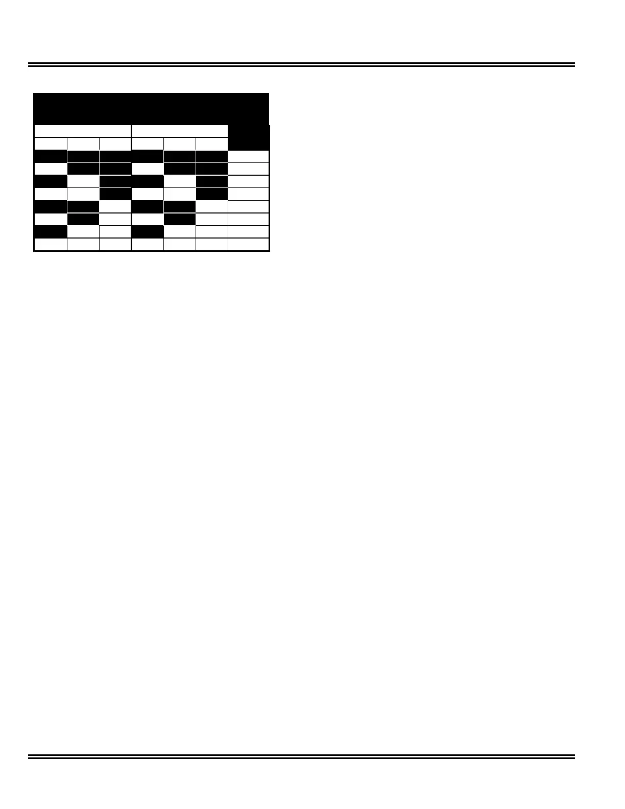
= OFF = ON
Alarm 1
(Set all 8 S2 switches)
Alarm 2
Reset
Level,
S3.C S3.C
%
S2.1 S2.2 S2.3 S2.4 S2.5 S2.6
off off off off off off 0
on off off on off off 10
off on off off on off 20
on on off on on off 30
off off on off off on 40
on off on on off on 50
off on on off on on 75
on on on on on on 100
Table 5.W Reset Threshold Settings
5.12.15.1 Overvoltage Reset Threshold
To determine the threshold level to reset the
overvoltage, find the voltage when an overvoltage alarm
will occur. This is the nominal AC line voltage (see
Section 5.5) multiplied by the overvoltage detection
level (see 5.12.12 p.29). Figure 5.1 (p.31) illustrates the
overvoltage set and reset levels.
The reset voltage is a percentage of the difference (0 to
100%) between the nominal voltage and the
overvoltage detection level, as determined by the reset
threshold. You can calculate this by:
OVR = OVDL - RST x (OVDL - NOM)
where
OVR = Overvoltage Reset (Volts)
RST = Reset Threshold
OVDL = Overvoltage Detection Level (Volts)
NOM = Nominal AC line Voltage (Volts)
 Loading...