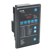
IQ DP-4000
SECTION 5 - PROGRAMMING THE IQ DP-4000 TD 17548B
23
4. Press the Save button briefly to see if the LED's
light properly. The corresponding LED will light if
the switch is turned on.
5. When the Setpoint Switches for that Rotary Select
Switch are all in the proper location, press and hold
the Save button until the tenth LED lights. The
settings are now stored permanently in the device's
non-volatile memory.
6. Repeat steps 1 to 5 for each Rotary Select Switch
position.
7. When you are done, set the Rotary Select Switch to
the 0 position.
5.2.1 Setpoint Switch Programming Example
As an example, let us program the device to accept
100:5 current transformers (CT’s). To do this:
1. Turn to Appendix A of this manual and look for the
size of CT’s that are being used (100:5).
= OFF = ON
= Not Applicable
Select Switch(S3) Setpoint Switch (S2)
Position 12345678
1
3
Table 5.E Setpoint Switch Settings
2. Turn the Rotary Select Switch to position 1 (S3.1).
As stated in Appendix A, set the Setpoint Switches
(S2) as shown in Table 5.E (gray indicates reserved
for other setpoints, black indicates OFF and white
indicates ON).
3. Push the eighth Setpoint Switch to the left (off).
When you press the Save button in step 9, you will
save all 8 switches and overwrite any previous
settings made for S3.1.
4. Briefly press the Save button to confirm the
settings. The 8th LED will not light indicating the off
position.
5. Press and hold the Save button until the tenth LED
lights. The setting for Rotary Select Switch position
1 (S3.1) is now permanently stored in the device's
long-term memory.
6. Turn the Rotary Select Switch to position 3 (S3.3).
7. Push the first, second and fifth Setpoint Switches to
the right (on). Push the third, fourth, sixth, seventh,
and eighth to the left (off).
8. Briefly press the Save button to confirm the
settings. The first, second, and fifths LEDs light
indicating they are in the on position.
9. Press and hold the Save button until the tenth LED
lights. The setting for Select Switch 3 is now
permanently stored in the device's long-term
memory.
10. Place the Select Switch to the 0 position.
5.3 SYSTEM CONFIGURATION SETPOINT
The IQ DP-4000 monitors either a 3-conductor or 4-
conductor AC line. For example, in a 4-wire system, a
transformer’s secondary winding is wired in a wye
configuration, with the XO neutral terminal ground as
the fourth wire. In this case, the XO fourth wire
connects to the screw terminal on the power supply.
Refer to Figures 4.9 and 4.15.
Record the desired Setpoint Switch setting S2.1, for
Rotary Switch position S3.1 in Appendix B as follows:
• OFF position for a 3-wire wiring configuration
• ON position for a 4-wire wiring configuration
When you choose the OFF position for the 3-wire
configuration, the front panel will not display the 3 line-
to-neutral AC line measurements. The measurements
not displayed are: You must set all 8 S2 switches
- V
A-N
Volts
- V
B-N
Volts
- V
C-N
Volts
5.4 FREQUENCY SELECTION SETPOINT
The IQ DP-4000 accepts a nominal line frequency of
either 50 or 60 Hz. Record the desired S2.2.setting for
Rotary Switch position S3.1: Set all 8 S2 switches
• OFF position for a 50 Hz system
• ON position for a 60 Hz system
5.5 NOMINAL AC LINE VOLTAGE SETPOINT
The IQ DP-4000 measures AC line voltage in one of
two ways:
• Line-to-line (3 Phase 3 Wire)
• Line-to-neutral (3 Phase 4 Wire)
Based on the wiring configuration for the system, you
must set switches to indicate the nominal AC line
voltage applied to the AC line terminals. Line-to-neutral
 Loading...