Eaton Power Xpert 9395 UPS Installation and Operation Manual 164201764—Rev 14 81
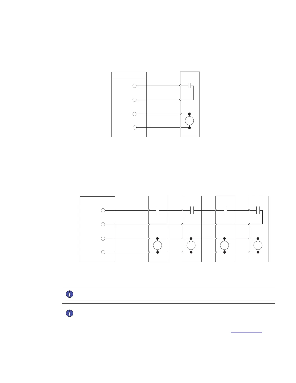
Figure 41. Typical Battery Interface Connection – Common Battery System
Battery
Breaker or
Disconnect
TB1
Battery Aux
Battery Aux Common
48 Vdc Battery Shunt Trip +
48 Vdc Battery Shunt Trip –
UPS
ST
5
6
7
8
NOTE Battery Aux and DC Shunt Trip wiring should beaminimum of 18 AWG.
Figure 42. Typical Battery Interface Connection – Separate Battery System
UPM 1
Battery
Disconnect
TB1
UPS
ST
UPM 2
Battery
Disconnect
ST
UPM 4
Battery
Disconnect
ST
UPM 3
Battery
Disconnect
ST
48 Vdc
Battery Aux
Battery Aux Return
48 Vdc Battery Shunt Trip +
5
6
7
8
NOTE Battery aux and DC shunt trip wiring should be a minimum of 18 AWG.
48 Vdc Battery Shunt Trip –
44..99..33 XX--SSlloott CCoonnnneeccttiioonnss
NOTE LAN and telephone drops for use with X-Slot cards must be provided by the customer.
NOTE When installing external wiring to X-Slot cards, conduit must be installed to the UPS
cabinet. When installing internal wiring to X-Slot terminals, route the wiring through the
internal opening in the X-Slot communication bay.
For installation and setup of an X-Slot card, contact an Eaton service representative (see 1.8 Getting Help).
To install wiring to connections:
UPS System Installation
 Loading...