114 Eaton Power Xpert 9395 UPS Installation and Operation Manual 164201764—Rev 14
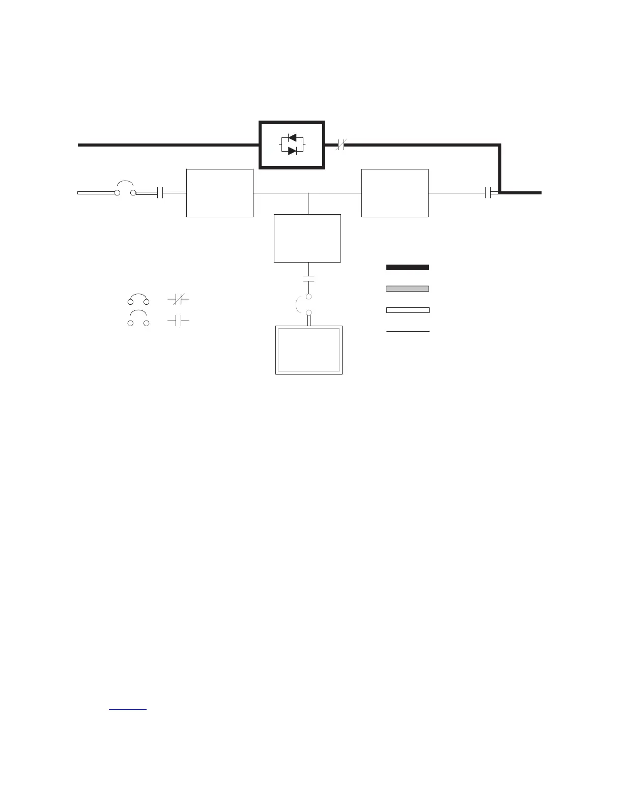
Figure 64. Path of Current Through the UPS in Bypass Mode
Static
Switch
K5
retrevnIreifitceR
K1 K3
Battery
Converter
Battery
Battery
Breaker
Main Power Flow
Trickle Current
Energized
De-Energized
Closed
Open
Breakers Contactors
K2
Bypass Input
Rectifier
Input
Output
Input
Breaker
(CB1
NOTE On a UPS configured as an IOM, the bypass input, static switch, bypass breaker (CB4), and K5 are not present.
NOTE On a UPS configured with a Continuous Static Switch (CSS), bypass breaker (CB4) is not present.
In Bypass mode, the output of the system is provided with three-phase AC power directly from the system
input. While in this mode, the output of the system is not protected from voltage or frequency fluctuations or
power outages from the source. Some power line filtering and spike protection is provided to the load but no
active power conditioning or battery support is available to the output of the system in the Bypass mode of
operation.
The internal bypass is comprised of a solid-state, silicon-controlled rectifier (SCR) static switch (SSW) and a
backfeed protection contactor K5. The static switch is rated as a continuous-duty device that is used anytime
the inverter is unable to support the applied load. The static switch is wired in series with the backfeed
protection contactor, and together they are wired in parallel with the rectifier and inverter.
The static switch, being an electronically-controlled device, can be turned on immediately to pick up the load
from the inverter while the inverter output contactor K3 opens to isolate the inverter. The backfeed protection
contactor is normally always closed, ready to support the static switch unless the bypass input source
becomes unavailable.
If the UPS transfers to Bypass mode from Online mode due to any reason other than operator intervention, the
UPS automatically attempts to transfer back to Online mode (up to three times within a ten minute period). The
fourth transfer locks the critical load to the bypass source and requires operator intervention to transfer.
66..22..77 BBaatttteerryy MMooddee
The UPS automatically transfers to Battery mode if a utility power outage occurs, or if the utility power does not
conform to specified parameters. In Battery mode, the battery provides emergency DC power that the inverter
converts to AC power.
Figure 65 shows the path of electrical power through the UPS system when operating in Battery mode.
Understanding UPS Operation
 Loading...