Battery Breaker
Battery
Converter
Inverter
K3
Fuse
Rectifier
K1
K2
Fuse
Fuse
Fuse
E6
E7
E8
E12
K5
Static
Switch
Fuse
E1
E2
E3
CB1
(optional)
UPS 1
A B
TIE
CABINET
(Optional)
E
AC Output to
Critical Load
E4. E5
BATTERY SYSTEM
MOB 1
MOB 2
(Not supplied
with the UPS)
C
E9,
E10,
E11,
E12
D
Battery Breaker
Battery
Converter
Inverter
K3
Fuse
Rectifier
K1
K2
Fuse
Fuse
Fuse
E6
E7
E8
E12
K5
Static
Switch
Fuse
E1
E2
E3
CB1
(optional)
UPS 2
A B
E4. E5
BATTERY SYSTEM
(Not supplied
with the UPS)
C
E9,
E10,
E11,
E12
D
*
***
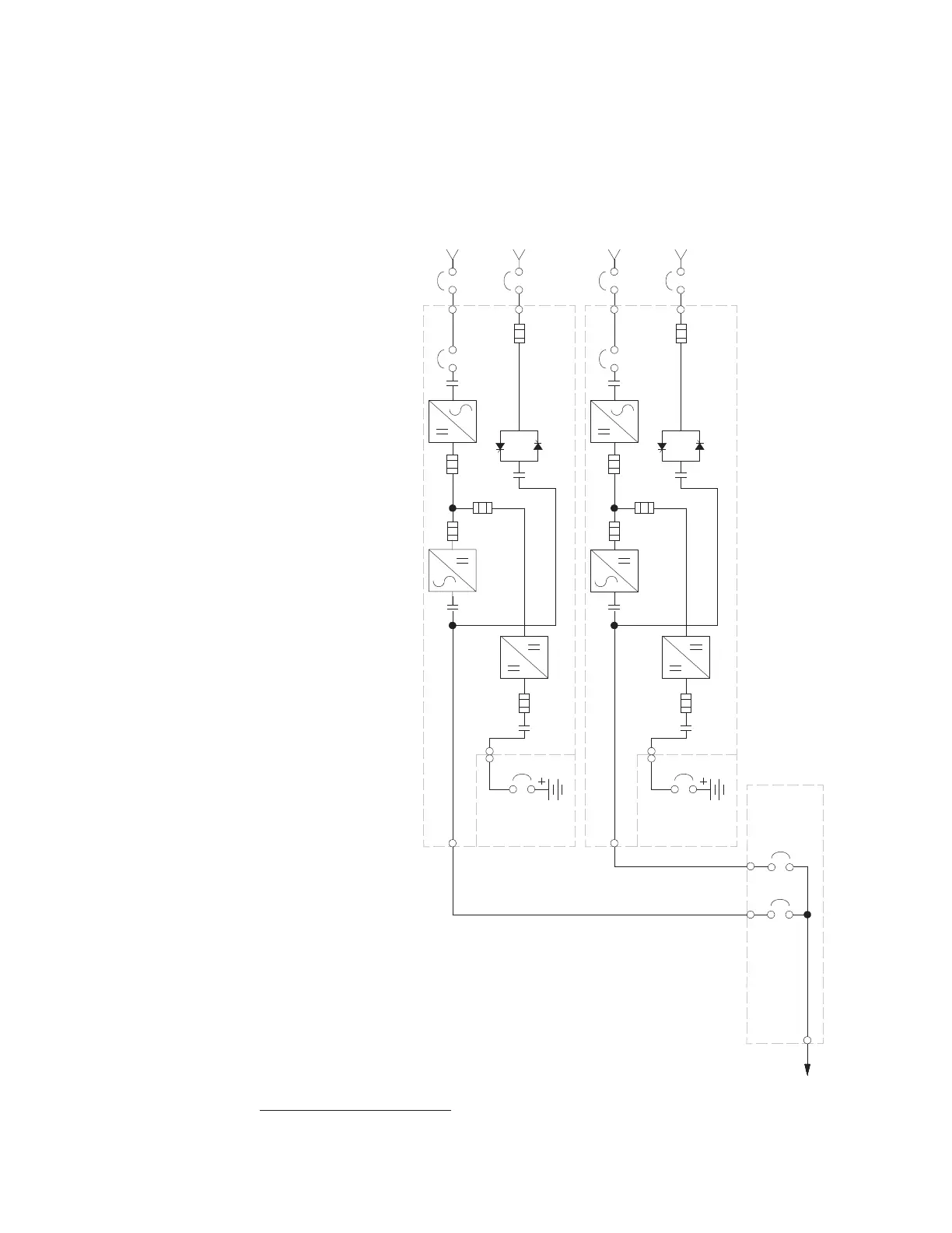
A – AC Input to UPS Rectifier
B – AC Input to Bypass
C – DC Input from Battery
D – UPS AC Output to Tie Cabinet
E – Output to Critical Load
* – Overcurrent Protection provided by customer
*
NOTE This oneline does not show each UPM in the UPSs, but represents each UPS in the distributed bypass system. The internal
structure of each UPS is shown in the Single UPS System Oneline Configurations Section 6.3.
NOTE If the load requires a neutral, a bypass source neutral must be provided. DO NOT install bothasource neutral andabonding jumper.
 Loading...