100 Eaton Power Xpert 9395 UPS Installation and Operation Manual 164201764—Rev 14
4. Remove the UPS cabinet top interface conduit landing plates to drill or punch conduit holes (see Figure 31).
5. Reinstall the conduit landing plate.
6. Install conduit between the UPS and RMP II. See Figure 59 for RMP II knockout hole location.
7. Install wiring between the UPS and RMP II. See Figure 49 and Table 23 for the Powerware Hot Sync CAN
Bridge Card terminal location and wiring information, and Figure 54, Figure 55, and Table 27 for the RMP II
terminal location and wiring information.
NOTE 120 Vac for the RMP II should be supplied from the critical bus by facility planners or the
customer.
8. Install 120 Vac power wiring from the critical bus to the RMP II. See Figure 54, Figure 55, and Table 27 for
the terminal location and wiring information.
9. Close the front door and secure the latch.
10. Restart the UPS. See Chapter 7 UPS Operating Instructions for startup instructions.
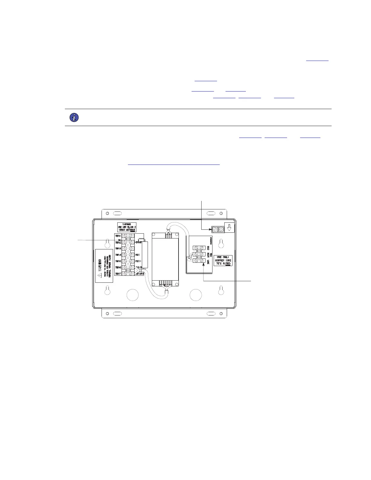
Figure 54. Remote Monitor Panel II and Remote Monitor Panel II Terminal Locations
Terminal TB1
Signal Connections
from the UPS
Ground
Terminal
Terminal TB3
120 Vac Power
Installing Options and Accessories
 Loading...