Safety
Information
Product
Information
Mechanical
Installation
Electrical
Installation
Getting
Started
Basic
parameters
Running
the motor
Optimization
SMARTCARD
operation
PC tools
Advanced
parameters
Technical
Data
Diagnostics
UL Listing
Information
226 Affinity User Guide
www.controltechniques.com Issue Number: 5
This method can also be used to set object identifier values below 32768
if required.
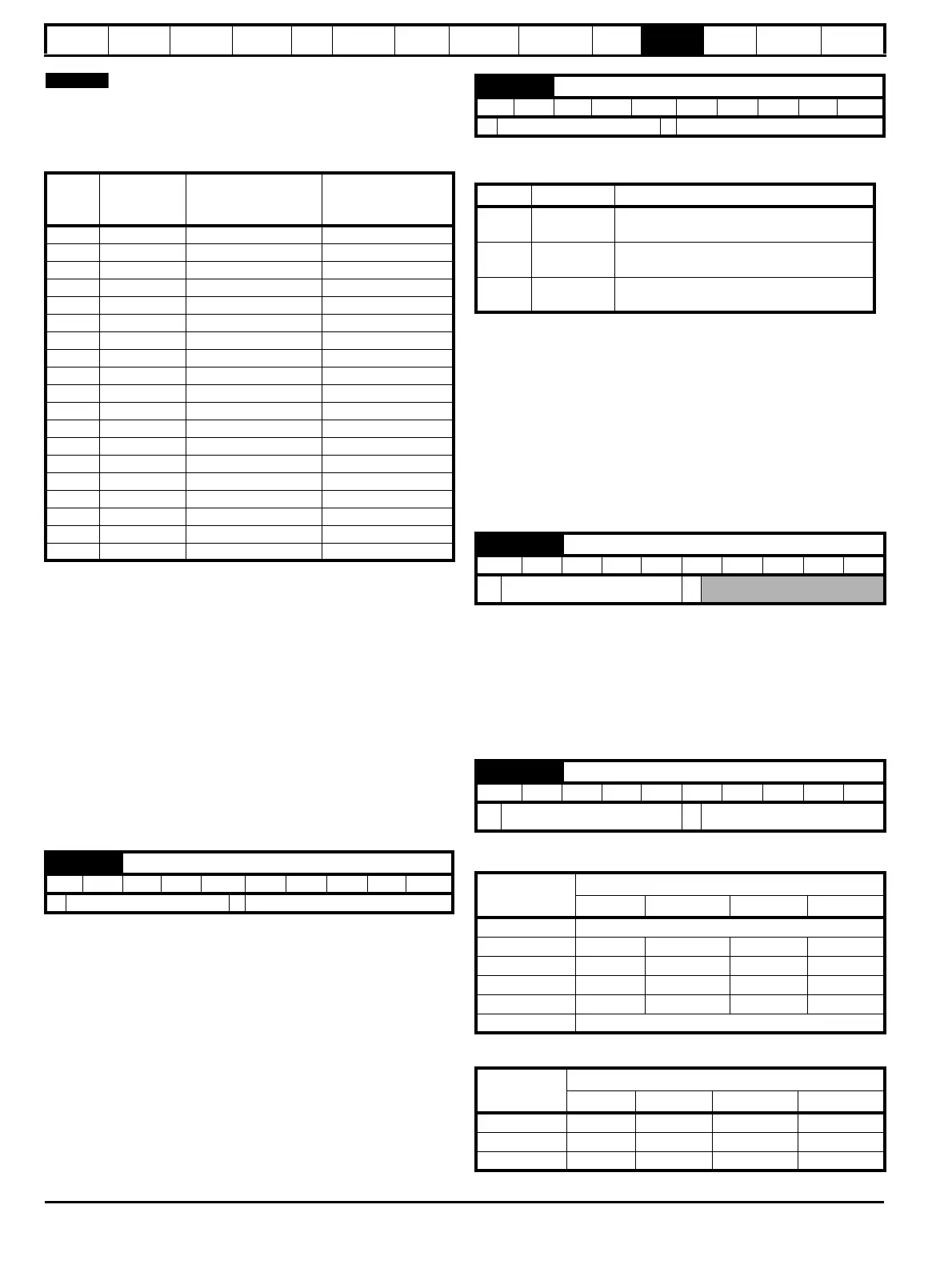
Table 11-11 Increased Object Identifier range setup
Example 1: To set the value of the Object Identifier as 4194302 for an
Affinity drive; set the following parameters (provided Pr 18.29 and
Pr 18.30 are not used for DPL program and are available);
•Pr 17.10 set to -19
•Pr 18.29 set to 4302
•Pr 18.30 set to 419
Example 2: To set the value of the Object Identifier as 59430 for an
Affinity drive; set the parameters (provided Pr 18.11 and Pr 18.12 are not
used for DPL program and are available);
•Pr 17.10 set to -1
•Pr 18.11 set to 9430
•Pr 18.12 set to 5
After setting the required Object Identifier, save the changes on the drive
Pr XX.00 = 1000.
This is the period of time in seconds that the drive will wait to see a valid
communications frame on the building automation network before taking
the action specified in Pr 17.13.
If the value specified is less than or equal to five then the timeout period
will be adjusted to be 5 seconds.
Care must be taken to ensure that this parameter is not set to a time less
than the minimum time period between frames on the network.
The following drive actions can be effected upon detection of
communications loss: -
The move to fixed speed option will only operate if the drive is configured
to use preset speed 1 as the reference at the time communications is
lost.
Every time there is a transition from the communications OK state to the
communications lost state the reference value set in preset speed 8 will
be transferred to preset speed 1 causing the drive to run at the speed
defined in preset speed 8.
The drive will continue to run at this speed until such time as the user
manually changes preset speed 1 via the keypad or communications
returns and a new speed reference is provided via the building
automation network.
If an error is detected in the message header or message body then this
count is incremented by one and the message disposed of.
This parameter should remain constant when the connection to the
building automation network is operating correctly.
The CRC error count is reset to zero in the following circumstances:
1. When another CRC error is detected after 32767 prior errors.
2. Upon power up or drive reset
This selects the data transmission format used for the selected protocol.
The default value when Pr 17.38 is set to 0 OR >4 is as follows:
Serial
No
Set value in
Pr 17.10
Enter last four
numbers from Object
Identifier
Enter first three
numbers from
Object Identifier
1 -1 Pr 18.11 Pr 18.12
2 -2 Pr 18.12 Pr 18.13
3 -3 Pr 18.13 Pr 18.14
4 -4 Pr 18.14 Pr 18.15
5 -5 Pr 18.15 Pr 18.16
6 -6 Pr 18.16 Pr 18.17
7 -7 Pr 18.17 Pr 18.18
8 -8 Pr 18.18 Pr 18.19
9 -9 Pr 18.19 Pr 18.20
10 -10 Pr 18.20 Pr 18.21
11 -11 Pr 18.21 Pr 18.22
12 -12 Pr 18.22 Pr 18.23
13 -13 Pr 18.23 Pr 18.24
14 -14 Pr 18.24 Pr 18.25
15 -15 Pr 18.25 Pr 18.26
16 -16 Pr 18.26 Pr 18.27
17 -17 Pr 18.27 Pr 18.28
18 -18 Pr 18.28 Pr 18.29
19 -19 Pr 18.29 Pr 18.30
17.12 Communications lost detection time-out period
RW Bi US
32768 to +32,767 60
17.13 Communications loss action
RW Bi US
32768 to +32,767 0
Pr 17.13 Action Comment
0 Do nothing
The drive will continue as it was before
communications was lost
1 Trip the drive
The drive will trip when communications is
lost
2
Move to a
fixed speed
Preset speed 8 is used to define this speed,
see below
17.35 CRC errors
RO Uni NC PT
Ú
0 to 2
31
-1
Ö
17.38 Data format
RW Bi US
Ú
0 to 255
Ö
0
Pr 17.38
Description
Start Bits Data Bits Parity Stop Bits
0 Protocol default value
1 1 8 None 1
2 1 8 None 2
318Even1
418Odd1
>4 Protocol default value
Protocol
Description
Start bits Data bits Parity Stop bits
Modbus RTU 1 8 None 2
BACnet 1 8 None 1
Metasys N2 1 8 None 1
 Loading...