Safety
Information
Product
Information
Mechanical
Installation
Electrical
Installation
Getting
Started
Basic
parameters
Running
the motor
Optimization
SMARTCARD
operation
PC tools
Advanced
parameters
Technical
Data
Diagnostics
UL Listing
Information
76 Affinity User Guide
www.controltechniques.com Issue Number: 5
Incorrect connection of the windings will cause severe under or over
fluxing of the motor, leading to a very poor output torque or motor
saturation and overheating respectively.
4.8.5 Output contactor
A contactor is sometimes required to be installed between the drive and
motor for safety purposes.
The recommended motor contactor is the AC3 type.
Switching of an output contactor should only occur when the output of
the drive is disabled.
Opening or closing of the contactor with the drive enabled will lead to:
1. OI.AC trips (which cannot be reset for 10 seconds)
2. High levels of radio frequency noise emission
3. Increased contactor wear and tear
4.9 Braking
Braking occurs when the drive is decelerating the motor, or is preventing
the motor from gaining speed due to mechanical influences. During
braking, energy is returned to the drive from the motor.
When the motor is being braked by the drive, the maximum regenerated
power that the drive can absorb is equal to the power dissipation
(losses) of the drive.
When the regenerated power is likely to exceed these losses, the DC
bus voltage of the drive increases. Under default conditions, the drive
brakes the motor under PI control, which extends the deceleration time
as necessary in order to prevent the DC bus voltage from rising above a
user defined set-point.
If the drive is expected to rapidly decelerate a load, or to hold back an
overhauling load, a braking resistor must be installed.
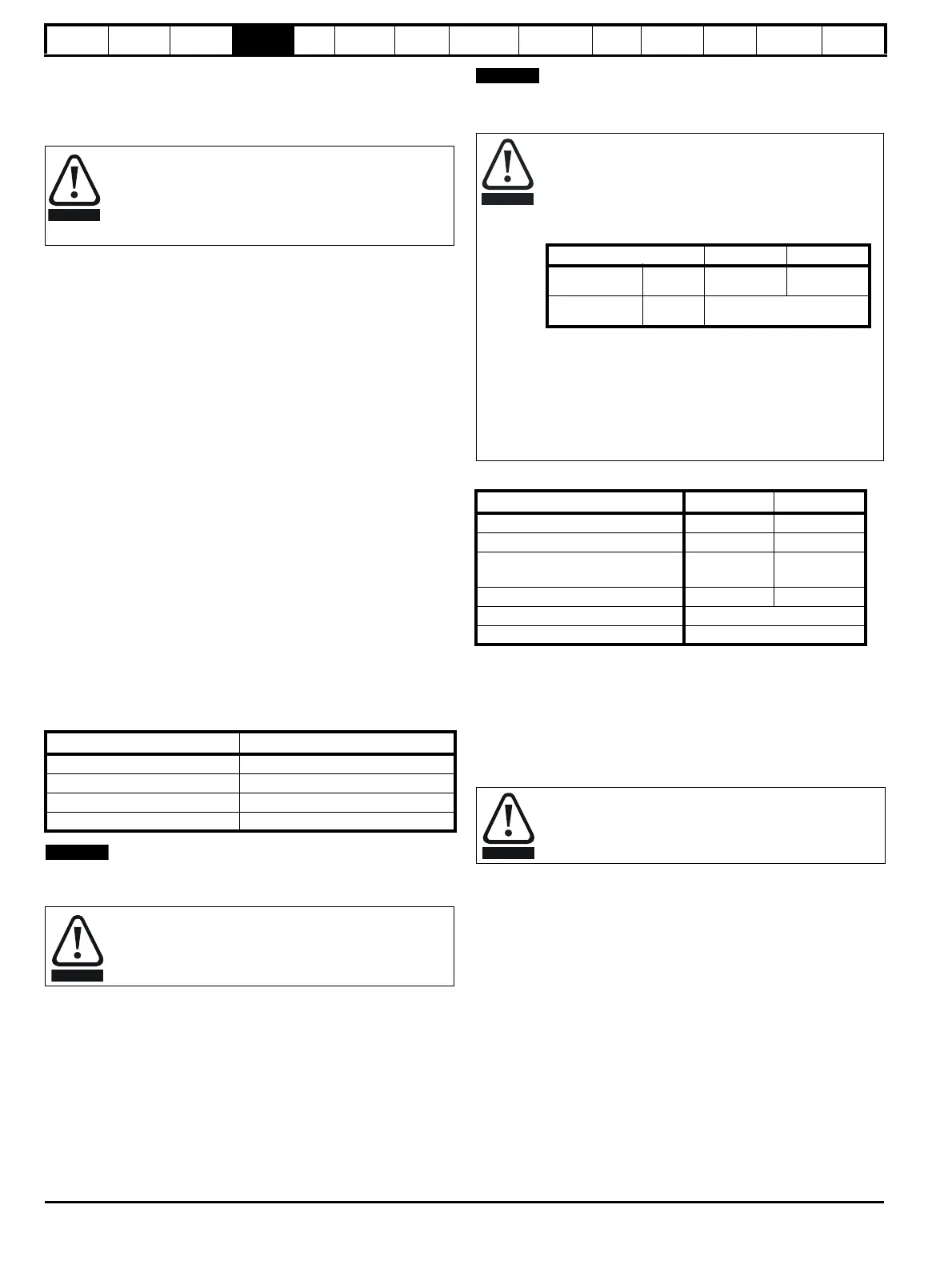
Table 4-10 shows the DC voltage level at which the drive turns on the
braking transistor.
Table 4-10 Braking transistor turn on voltage
N
When a braking resistor is used, Pr 0.15 should be set to FASt ramp
mode.
4.9.1 Heatsink mounted braking resistor
A resistor has been especially designed to be mounted within the
heatsink of the drive (sizes 1 and 2). See the Installation Sheet provided
with the heatsink mounted braking resistor. The design of the resistor is
such that no thermal protection circuit is required, as the device will fail
safely under fault conditions. On sizes 1 and 2, the in built software
overload protection is set up at default for the designated heatsink
mounted resistor. Table 4-11 provides the resistor data for each drive
rating.
N
The heatsink mounted resistor is suitable for applications with a low level
of regen energy only. See Table 4-11.
Table 4-11 Heatsink mounted braking resistor data
* To keep the temperature of the resistor below 70°C (158°F) in a 30°C
(86°F) ambient, the average power rating is 50W for size 1 and 100W for
size 2. The above parameter settings ensure this is the case.
Size 3 and larger do not have heatsink mounted braking resistors, hence
the default values of Pr 10.30 and Pr 10.31 are 0 (i.e. software braking
resistor overload protection disabled).
4.9.2 External braking resistor
When a braking resistor is to be mounted outside the enclosure, ensure
that it is mounted in a ventilated metal housing that will perform the
following functions:
• Prevent inadvertent contact with the resistor
• Allow adequate ventilation for the resistor
When compliance with EMC emission standards is required, external
connection requires the cable to be armored or shielded, since it is not
fully contained in a metal enclosure. See section 4.11.5 Compliance with
generic emission standards on page 84 for further details.
Internal connection does not require the cable to be armored or
shielded.
If the cable between the drive and the motor is to be
interrupted by a contactor or circuit breaker, ensure that the
drive is disabled before the contactor or circuit breaker is
opened or closed. Severe arcing may occur if this circuit is
interrupted with the motor running at high current and low
speed.
Drive voltage rating DC bus voltage level
200V 390V
400V 780V
575V 930V
690V 1120V
High temperatures
Braking resistors can reach high temperatures. Locate
braking resistors so that damage cannot result. Use cable
having insulation capable of withstanding high temperatures.
Braking resistor overload protection parameter
settings. Failure to observe the following
information may damage the resistor.
The drive’s software contains an overload protection
function for a braking resistor. On size 1 and 2 this function
is enabled at default to protect the heatsink mounted
resistor. Below are the parameter settings.
For more information on the braking resistor software
overload protection, see Pr 10.30 and Pr 10.31 full
descriptions in the Advanced User Guide.
If the heatsink mounted braking resistor is to be used at
more than half of its average power rating then the drive's
cooling fan must be at full speed controlled by setting
Pr 6.45 to On (1).
Parameter Size 1 Size 2
Part number 1220-2756-01 1220-2758-01
DC resistance at 25°C75Ω 37.5Ω
Peak instantaneous power over
1ms at nominal resistance
8kW 16kW
Average power over 60s * 50W 100W
Ingress Protection (IP) rating IP54
Maximum altitude 2000m
Overload protection
When an external braking resistor is used, it is essential that
an overload protection device is incorporated in the braking
resistor circuit; this is described in Figure 4-14 on page 77.
Parameter 200V drive 400V drive
Full power
braking time
Pr
10.30
0.09 0.02
Full power
braking period
Pr
10.31
3.3
 Loading...