Safety
Information
Product
Information
Mechanical
Installation
Electrical
Installation
Getting
Started
Basic
parameters
Running
the motor
Optimization
SMARTCARD
operation
PC tools
Advanced
parameters
Technical
Data
Diagnostics
UL Listing
Information
Affinity User Guide 233
Issue Number: 5 www.controltechniques.com
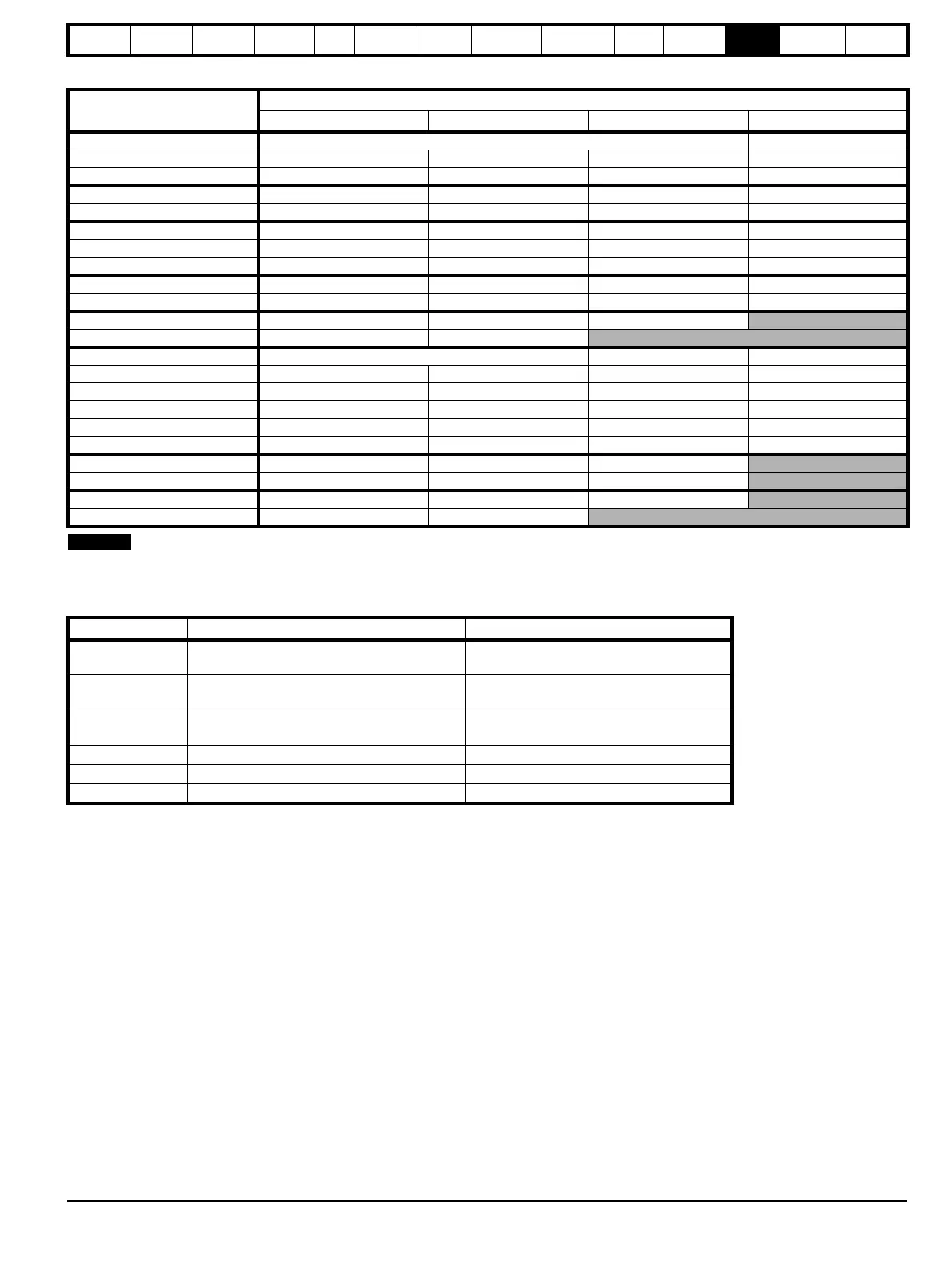
Table 12-7 Maximum permissible continuous output current @ 45°C (113°F) ambient for size 4 to 6 E12/54 drives
For the definition of ambient temperature, see section 3.7 Enclosure design and drive ambient temperature on page 49.
12.1.2 Power dissipation
Table 12-8 Summary of drive losses tables
Model
Maximum permissible continuous output current (A) for the following switching frequencies
3kHz 4kHz 6kHz 8kHz
BA4201-E12/54 68.0 61.3
BA4202-E12/54 80.0 78.8 69.1 61.3
BA4203-E12/54 84.4 78.7 69.1 61.3
BA5201-E12/54 106.5 95.1 76.9 63.2
BA5202-E12/54 106.5 95.1 77.0 63.2
BA4401-E12/54 52.6 46.1 36.2 29.1
BA4402-E12/54 52.6 46.0 36.2 29.1
BA4403-E12/54 55.3 48.2 37.3 29.5
BA5401-E12/54 92.6 80.1 61.7 48.9
BA5402-E12/54 92.6 80.1 61.6 48.8
BA6401-E12/54 99.7 82.5 58.0
BA6402-E12/54 91.1 72.1
BA4601-E12/54 22.0 16.6 12.9
BA4602-E12/54 26.7 22.5 16.6 12.8
BA4603-E12/54 26.7 22.4 16.6 12.8
BA4604-E12/54 26.7 22.4 16.6 12.8
BA4605-E12/54 26.7 22.4 16.5 12.8
BA4606-E12/54 29.7 24.9 18.1 13.8
BA5601-E12/54 38.7 31.0 21.2
BA5602-E12/54 38.7 30.9 21.3
BA6601-E12/54 46.4 36.9 25.4
BA6602-E12/54 46.2 36.9
Table Description Applicable drives
Table 12-9 Losses @ 40°C (104°F) ambient
Size 1 to 6 standard, 1 to 3 E12/E54 and 1 to
3 E12/E66
Table 12-10
Losses @ 40°C (104°F) ambient with IP54
insert and standard fan installed
Size 1 and 2 standard
Table 12-11 Losses @ 50°C (122°F) ambient
Size 1 to 6 standard,1 to 3 E12/E54 and 1 to
3 E12/E66
Table 12-12 Losses @ 35°C (95°F) ambient Size 4 to 6 E12/54
Table 12-13 Losses @ 40°C (104°F) ambient Size 4 to 6 E12/54
Table 12-14 Losses @ 45°C (113°F) ambient Size 4 to 6 E12/54
 Loading...