Safety
Information
Product
Information
Mechanical
Installation
Electrical
Installation
Getting
Started
Basic
parameters
Running
the motor
Optimization
SMARTCARD
operation
PC tools
Advanced
parameters
Technical
Data
Diagnostics
UL Listing
Information
Affinity User Guide 67
Issue Number: 5 www.controltechniques.com
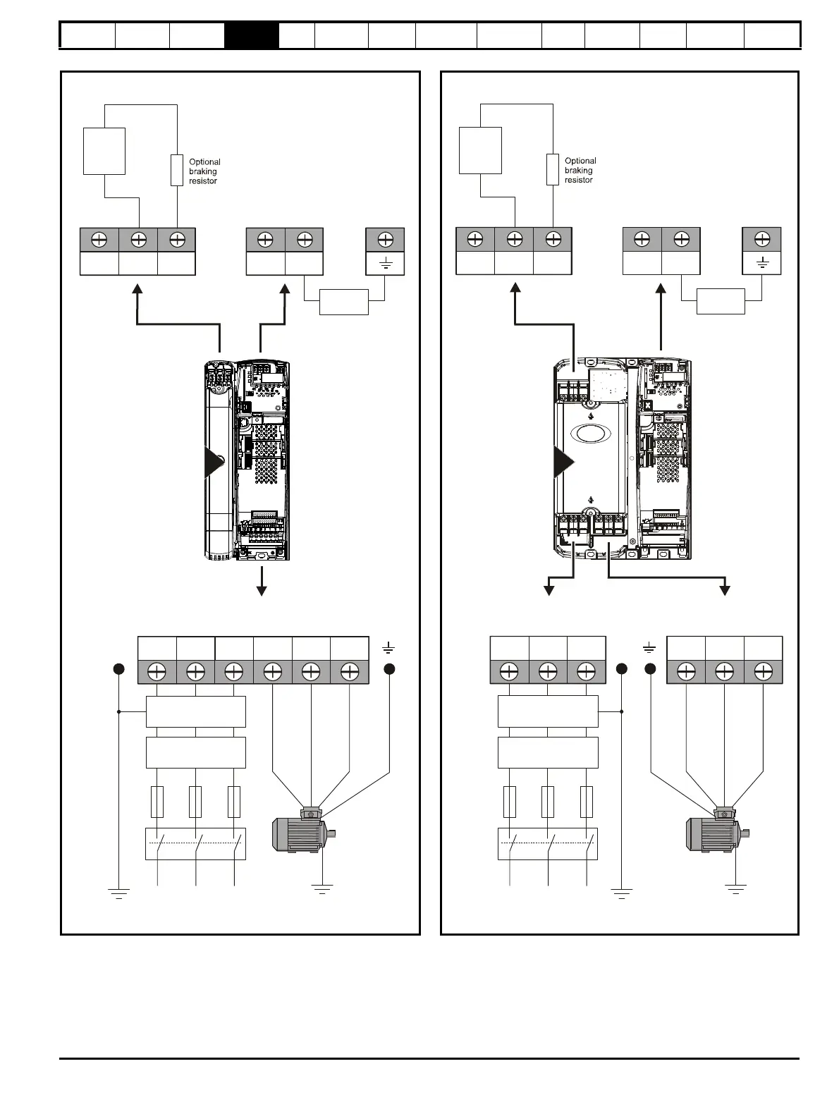
Figure 4-2 Size 2 power connections
If the heatsink mounted resistor is used (size 1 and 2 only), an overload
protection device is not required. The resistor is designed to fail safely
under fault conditions.
See Figure 4-5 for further information on ground connections.
Figure 4-3 Size 3 power connections
On size 2 and 3, the high current DC connections must always be used
when using a braking resistor, supplying the drive from DC (low voltage DC
or high voltage DC) or using the drive in a parallel DC bus system. The low
current DC connection is used to connect low voltage DC to the drive
internal power supply and to connect the internal EMC filter.
See Figure 4-6 for further information on ground connections.
2
L1 L2
L2L1 L3 U V W
Optional EMC
filter
Optional
line reactor
Fuses
L3
Mains
Supply
Motor
Optional ground
connection
Supply
Ground
BR
Thermal
overload
protection
device
DC1 DC2
DC Connections
(High current DC and braking)
-DC +DC
DC Connections
(Low current DC)
Internal
EMC filter
DC1 =
DC2 = +
-
BR
Thermal
overload
protection
device
DC1 DC2
DC Connections
(High current DC and braking)
 Loading...