Installation Guide
21
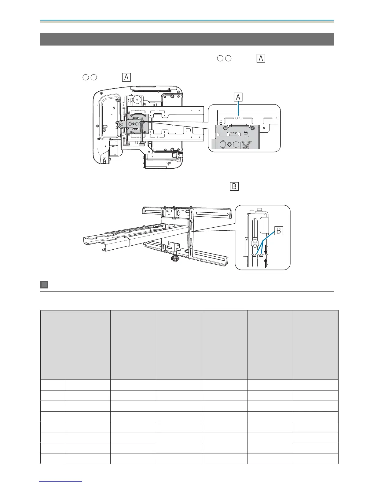
When Projected Image is 75 inches or more
Mount the 3-axis adjustment unit at the position marked with a stamp ( ).
The projection distance table provides the figures when mounting the 3-axis adjustment unit at the position
marked with a
stamp ( ).
The distance from the top of the projected image to the bottom wall plate installation screw hole (c) is the
number given when the vertical slide is set to the standard position (
).
Match the notch on the setting plate to the position of the stamp on the wall plate.
EB-685W/EB-675W (16:10 projected image)
[Unit: cm]
S
Projected image size
a
Projection Dis-
tance
Minimum
(Wide) to Maxi-
mum (Tele)
b
Numbers on
the arm slide
scale
c
Distance to the
bottom wall
plate installa-
tion screw hole
d
Distance from
the top of the
projected im-
age to the wall
plate tempora-
ry securing
screw hole
h
Height of pro-
jected image
75" 161.5x101.0 13.1 to 29.3 15.1 to 31.3 21.7 40.9 101.0
76" 163.7x102.3 13.7 to 30.1 15.7 to 32.1 22.0 41.2 102.3
77" 165.9x103.7 14.3 to 30.9 16.3 to 32.9 22.3 41.5 103.6
78" 168.0x105.0 14.9 to 31.8 16.9 to 33.8 22.6 41.8 105.0
79" 170.2x106.3 15.5 to 32.6 17.5 to 34.6 22.8 42.0 106.4
80" 172.3x107.7 16.1 to 33.5 18.1 to 35.5 23.1 42.3 107.7
81" 174.5x109.0 16.8 to 34.3 18.8 to 36.3 23.4 42.6 109.0
82" 176.6x110.4 17.4 to 35.1 19.4 to 37.1 23.7 42.9 110.4
 Loading...