Maintenance 6. Arm #2
132 G6 Rev.21
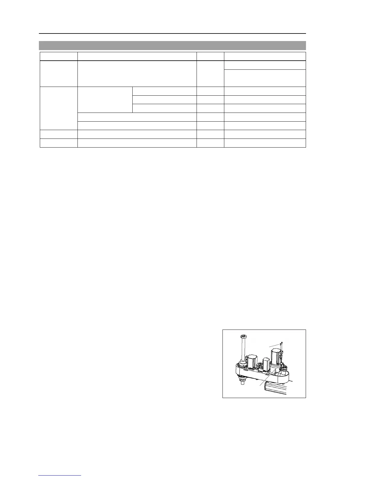
6.1 Replacing Joint #2 Motor
Maintenance
Parts
AC Servo Motor (400W) 1
Push down the shaft to its lower limit while pressing the brake release switch. Be
sure to keep enough space and prevent
the end effector hitting any
The brake release switch is applied to bo
th Joints #3 and #4. When the brake release
switch is pressed, the respective brakes of the Joints #3 and #4 are released
simultaneously.
(Joint #4 brake is installed to G6-**3** only.)
shaft falling and rotating while the brake release switch is
because the shaft may be lowered by the weight of an end effector.
Remove the arm top cover.
For details, refer to Maintenance: 3.1 Arm Top Cover.
Disconnect the connectors X22, X33
connected to the arm top cover.
Cut off the wire tie used for binding the motor cables to the Joint #2 motor.
Disconnect the connectors.
Connectors X221, X21 (Hold the claw to remove.)
Connector X62
 Loading...


