Maintenance 7. Arm #3
G6 Rev.21 145
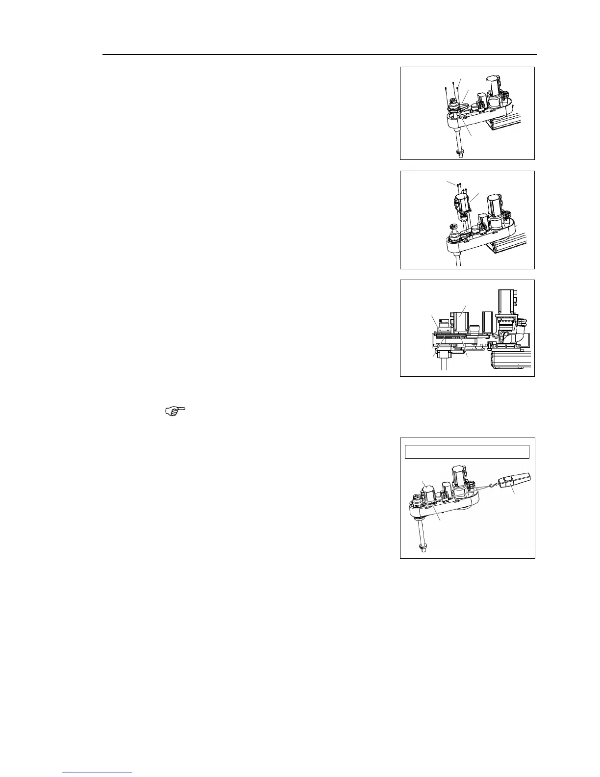
a new Z belt through the shaft from above,
and then place it under the spline plate.
Loosely secure the spline plate to Arm #2.
After moving the shaft up
times, secure the spline plate to Arm #2.
Set the Joint #3 motor unit in the arm so that
motor cable faces toward the back of the arm.
Place the Z belt around the Z1 pulley and the Z2
pulley so that the gear grooves of the belt are fit
into those of the pulleys completely.
Loosely secure the Joint #3 motor unit to Arm
Loosely secure the Joint #3 motor unit to Arm
#2 so that the motor unit
, and it will not tilt when pulled. If the unit is secured too loose or too tight
Apply the proper tension to the Z belt, and then
secure the Joint #3 motor unit.
a suitable cord or string around
the Joint #3 motor unit near its mounting plate
ull the cord using a force gauge or
similar tool to apply the specified tension
shown in the figure on the right
Make sure that the brake cables do not touch
the pulle
Z belt tension = 80 N (8.2 kgf)
.
Connectors X231, X31, X32, X63
-bundle the cables in their original positions with a wire tie removed in step (5).
allow unnecessary strain on the cables.
top cover and the arm bottom cover.
For details, refer to Maintenance: 3. Covers.
Perform the calibration of Joint #3.
For details, refer to Maintenance: 13. Calibration.
 Loading...


