Maintenance 8. Arm #4
G6 Rev.21 151
Push down the shaft to its lower limit while pressing the brake release switch. Be
sure to keep enough space and prevent the
hitting any peripheral
equipment.
The brake release switch is applied to both Joints #3 and #4. When the brake release
switch is pressed, the respective brakes of the Joints #3 and #4 are released
simultaneously.
(The brake for Joint #4 is only installed to G6-**3**.)
shaft falling and rotating while the brake release switch is
because the shaft may be lowered by the weight of an end effector.
top cover and the arm bottom cover.
For details, refer to Maintenance: 3. Covers.
Cut off the wire tie used for binding the motor cables to
Disconnect the following connectors.
(X42: G6-**3** only)
Connectors X241, X41 (Hold the claw to remove.)
Connector X42, X64
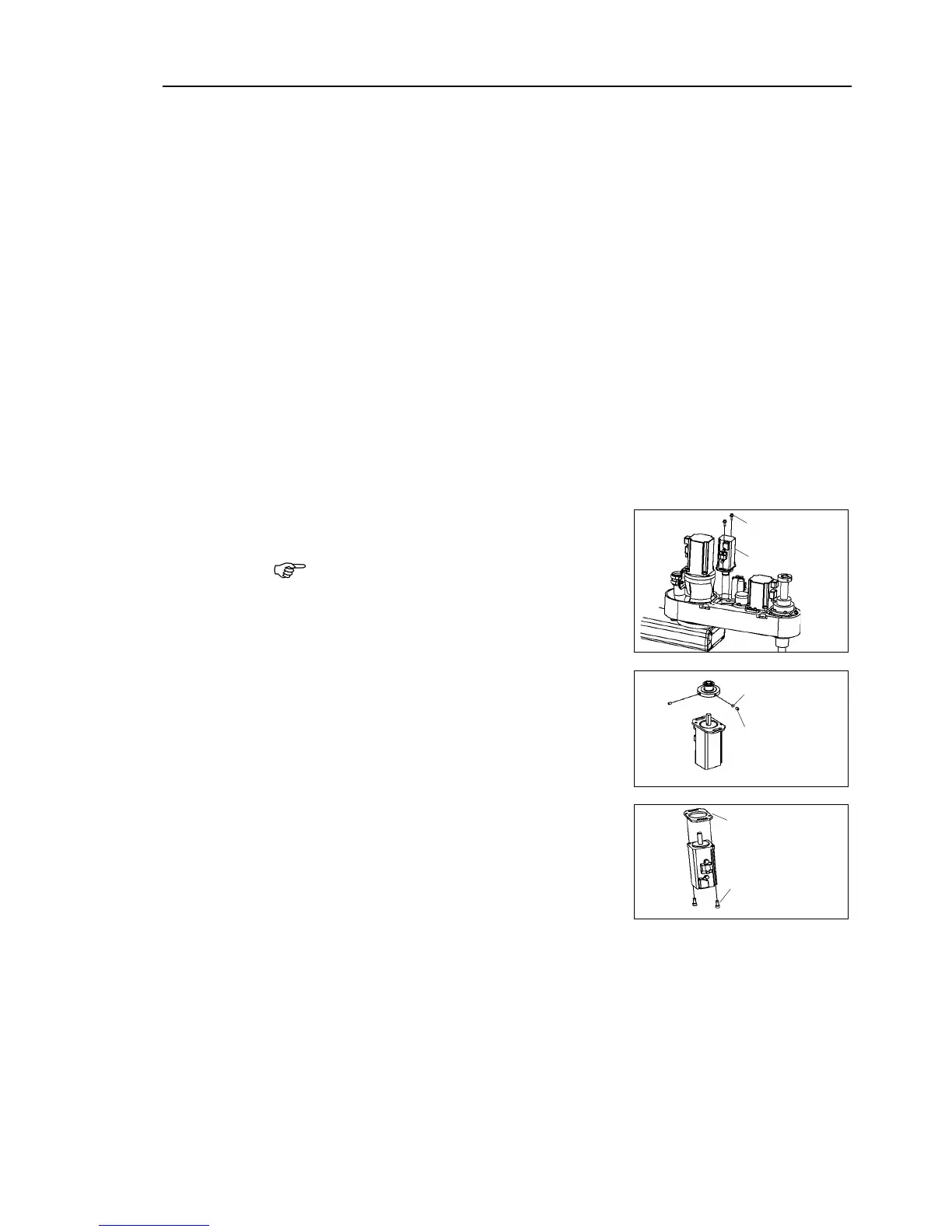
Remove the Joint #4 motor unit from Arm
Be careful not to break the battery board.
Unscrew the bolts securing the Joint #4 motor
unit to the Motor plate. Remove the U1 belt
from the pulley. Pull the Joint #4 motor unit
upward to remove.
the pulley from the Joint #4 motor.
There is a brass bushing in one of the
. Be careful not to lose it.
Remove the motor plate from the Joint #4
motor.
 Loading...


