Maintenance 9. Bellows
166 G6 Rev.21
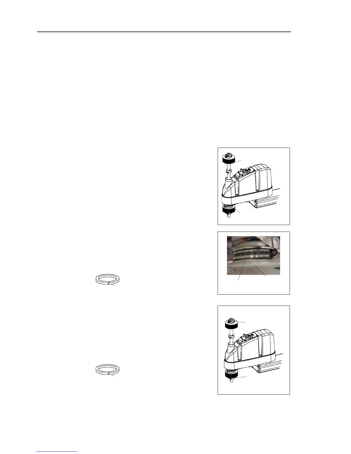
bellows, move the shaft to its lower limit.
To attach the lower bellows, move the shaft to its upper limit.
To move the shaft up/down, press and hold the brake release switch.
Be sure to keep enough space and prevent t
hitting any peripheral
equipment.
The brake release switch is applied to both Joints #3 and #4. When the brake
release switch is pressed, the respective brakes of the Joints #3 and #4 are released
simultaneously.
(The brake for Joint #4 is only installed to G6-**3**.)
shaft falling and rotating while the brake release switch is being
because the shaft may be lowered by the weight of an end effector.
Pass the shaft through the bellows
Secure the cover side of the bellows.
The bellows has two joints:
The larger joint must be attached to the cover side.
The smaller joint must be attached to the end face
side of the shaft.
Be careful not to misplace the clamp bands. The
clamp band has
three sizes; small, medium, and
Attach the mounting part of the bellows
cylindrical part of the cover.
Attach the rubber sheet. Be sure to attach the
rubber sheet so that no space is made between the
bias cut. (No rubber
sheet for the upper bellows
Then, secure them with clamp bands.
Secure the end face side of the bellows to the shaft.
over the bearing case (black) on the end face of
the bellows mounting part.
Attach the rubber sheet. Be sure to attach the
rubber sheet so that no space is made between the
bias cut.
Then, secure them with cl
After completing the attachment of the bellows, move the shaft up/down by hand
several times
ake sure that the bellows can expand and
contract smoothly without any excessive force.
 Loading...


