Maintenance 10. Ball Screw Spline Unit
176 G6 Rev.21
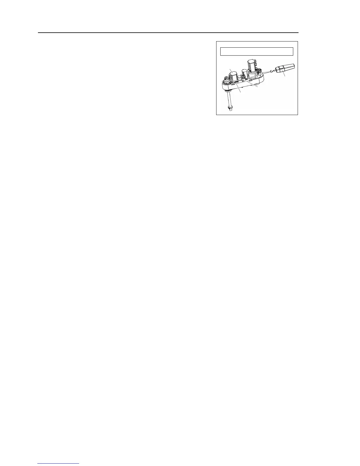
Apply the proper tension to the Z belt, and then
secure the Joint #3 motor unit.
To do so, pass a suitable cord or string around
the Joint #3 motor unit near its mounting plate.
Then, pull the cord using a force gauge or
similar tool to apply the specified tension shown
in the figure on the right.
Make sure that the brake cables do not touch the
pulley.
Z belt tension = 80 N (8.1 kgf)
Connect the connectors.
Connectors X231, X31, and X32
Re-bundle the cables in their original positions with a wire tie removed in step (4).
Do not allow unnecessary strain on the cables.
If the position of the lower
limit mechanical stop was changed for area limit, secure it
Grease the shaft.
For details, refer to Maintenance: 10.1. Greasing the Ball Screw Spline Unit.
Install the arm top cover and arm bottom cover.
For details, refer to Maintenance: 3. Covers.
Turn OFF the Controller and peripheral equipment.
Install the end effector, and connect wires and tubes to the end effector.
This step is only for Cleanroom-model and Protected-model (C, D
option, P).
Install the bellows.
For details, refer to Maintenance: 9. Bellows.
Perform the calibration of Joints #3 and #4.
For details, refer to Maintenance: 13. Calibration.
 Loading...


