139
Appendix
RS-232 Serial Interface (Serial model)
Interface board specifications (RS-232-compliant)
Functions of each connector pin
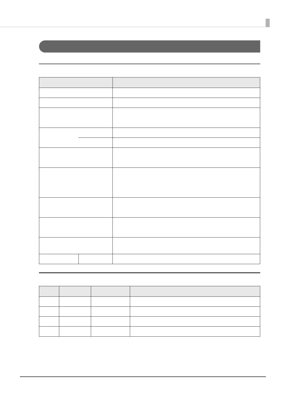
Item Specifications
Data transfer method Serial
Synchronization Asynchronous
Handshake Select one of the following with DIP switch 1-3:
• DTR/DSR • XON/XOFF
Signal level MARK -3V to -15V logic “1”/OFF
SPACE +3V to +15V logic “0”/ON
Bit length Select one of the following with DIP switch 1-4:
• 7 bit • 8 bit
Transmission speed
[bps: bits per second]
• Select one of the following with DIP switch 1-7/1-8:
4800/9600/19200/38400 bps
• Select one of the following with commands:
2400/4800/9600/19200/38400/57600/115200 bps
Parity check Select one of the following with DIP switch 1-5:
• Yes • No
Parity selection Select one of the following with DIP switch 1-6:
• Even • Odd
Stop bit 1 or more bits
However, the stop bit for data transfer from the printer is fixed to 1 bit.
Connector Printer side DSUB 25-pin (female) connector
Pin no. Signal name Signal direction Function
1FG — Frame ground
2 TXD Output Transmission data
3 RXD Input Reception data
4 RTS Output Equivalent to DTR signal (pin 20)
 Loading...