Instruction Manual
D103409X012
Detailed Setup
May 2013
54
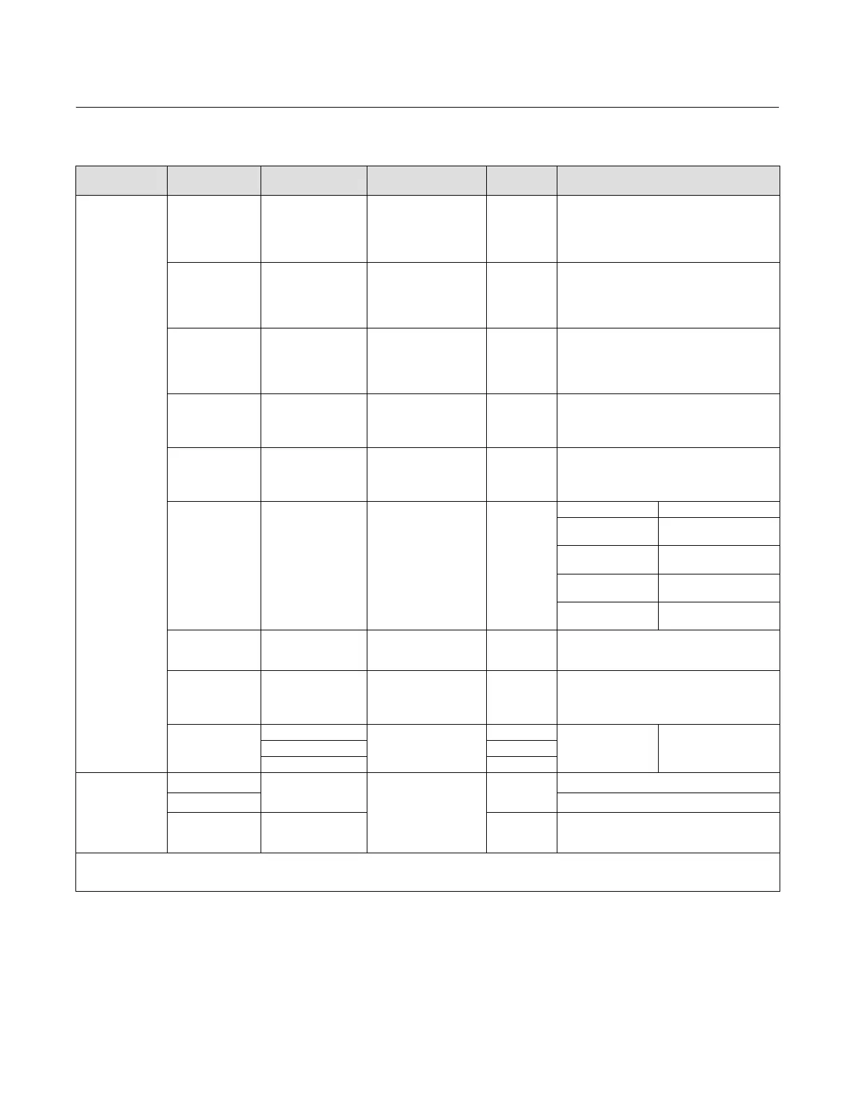
Table 4‐4. Actuator Information for Initial Setup
Actuator
Manufacturer
Actuator Model Actuator Size Actuator Style
Starting
Tuning Set
Travel Sensor Motion
(2)
Relay A or C
(3)
Fisher
585C & 585CR
25
50
60
68, 80
100, 130
Piston Dbl w/ or w/o
Spring. See actuator
instruction manual and
nameplate.
E
I
J
L
M
User Specified
657
30
34, 40
45, 50
46, 60, 70, 76, &
80‐100
Spring & Diaphragm
H
K
L
M
Away from the top of the instrument
667
30
34, 40
45, 50
46, 60, 70, 76, &
80‐100
Spring & Diaphragm
H
K
L
M
Towards the top of the instrument
1051 & 1052
20, 30
33
40
60, 70
Spring & Diaphragm
(Window‐mount)
H
I
K
M
Away from the top of the instrument
1061
30
40
60
68, 80, 100, 130
Piston Dbl w/o Spring
J
K
L
M
Depends upon pneumatic connections. See
description for Travel Sensor Motion
1066SR
20
27, 75
Piston Sgl w/Spring
G
L
Mounting Style Travel Sensor Motion
A
Away from the top of
the instrument
B
Towards the top of the
instrument
C
Towards the top of the
instrument
D
Away from the top of
the instrument
2052
1
2
3
Spring & Diaphragm
(Window‐mount)
H
J
M
Away from the top of the instrument
3024C
30, 30E
34, 34E, 40, 40E
45, 45E
Spring & Diaphragm
E
H
K
For P
o
operating mode (air opens):
Towards the top of the instrument
For P
s
operating mode (air closes):
Away from the top of the instrument
GX
225
Spring & Diaphragm
X
(1)
Air to Open
Towards the top of
the instrument
Air to Close
Away from the top of
the instrument
750 K
1200 M
Baumann
Air to Extend
16
32
54
Spring & Diaphragm
C
E
H
Towards the top of the instrument
Air to Retract Away from the top of the instrument
Rotary
10
25
54
E
H
J
Specify
NOTE: Refer to figure 2‐3 and table 4‐8 for feedback connection (magnet assembly) information.
1. X = Expert Tuning. Proportional Gain = 4.2; Velocity Gain = 3.0; Minor Loop Feedback Gain = 18.0
2. Travel Sensor Motion in this instance refers to the motion of the magnet assembly.
3. Values shown are for Relay A and C. Reverse for Relay B.

 Loading...


