Instruction Manual
D103409X012
Detailed Setup
May 2013
72
D For instruments with Relay B: If decreasing air pressure at output B causes the magnet assembly to down, or the
rotary shaft to turn clockwise, enter CW/To Bottom Inst. If it causes the magnet assembly to move up, or the rotary
shaft to turn counterclockwise, enter CCW/To Top Inst.
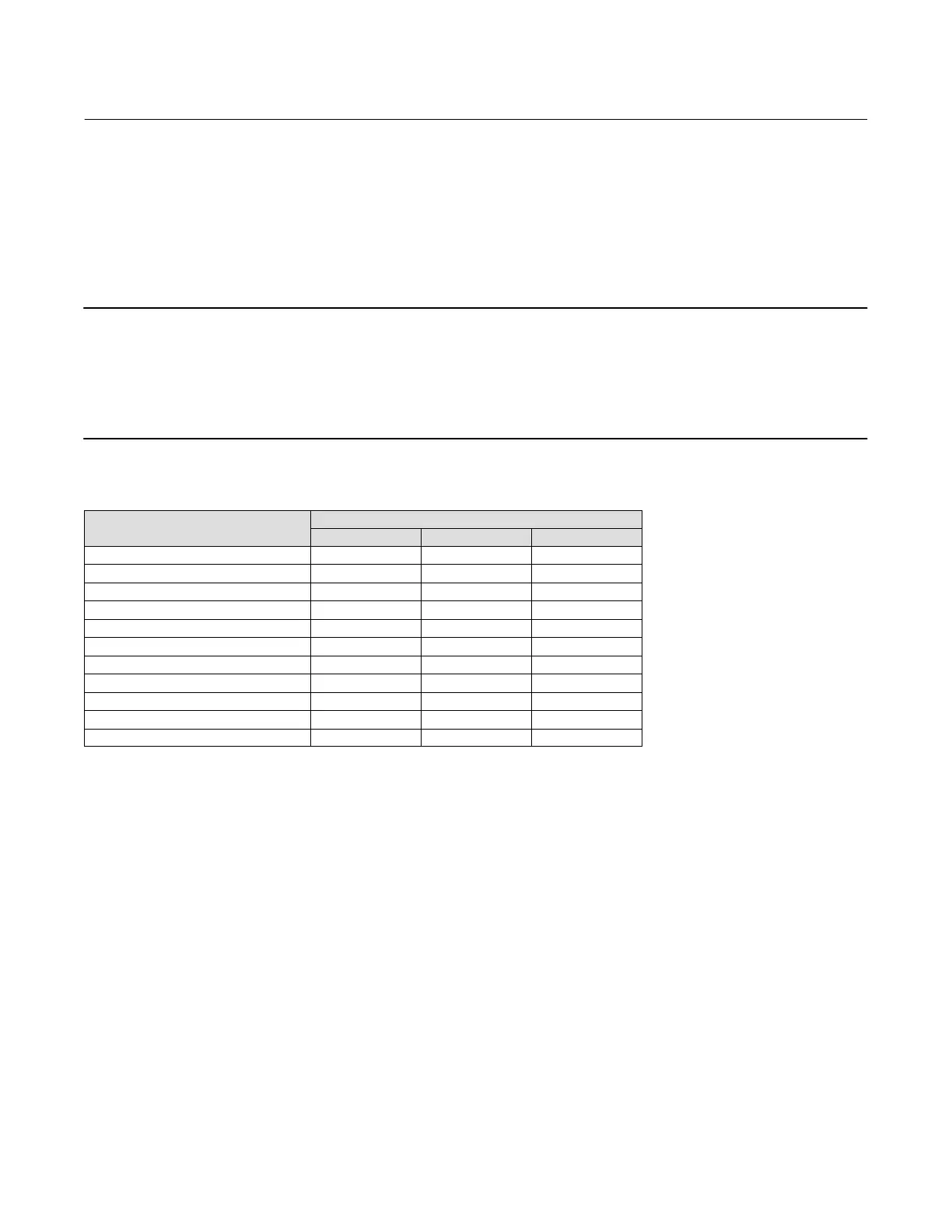
View / Edit Feedback Connection—Refer to table 4‐8 for Feedback Connection options. Choose the assembly that
matches the actuator travel range.
Note
As a general rule, do not use less than 60% of the magnet assembly travel range for full travel measurement. Performance will
decrease as the assembly is increasingly subranged.
The linear magnet assemblies have a valid travel range indicated by arrows molded into the piece. This means that the hall sensor
(on the back of the DVC6200 housing) has to remain within this range throughout the entire valve travel. See figure 2‐2. The linear
magnet assemblies are symmetrical. Either end may be up.
Table 4‐8. Feedback Connection Options
Magnet Assembly
Travel Range
mm Inch Degrees
Sstem #7 4.2-7 0.17-0.28 -
SStem #19 8-19 0.32-0.75 -
SStem #25 20-25 0.76-1.00 -
SStem #38 26-38 1.01-1.50 -
SStem #50 39-50 1.51-2.00 -
SStem #100 51-100 2.01-4.00 -
SStem #210 101-210 4.01-8.25
SStem #1 Roller - - 60-90_
RShaft Window #1 - - 60-90_
RShaft Window #2 - - 60-90_
RShaft End Mount - - 60-90_
Assembly Specification Sheet— Allows you to view and edit the Specification Sheet used by ValveLink software.

 Loading...


