Instruction Manual
D103409X012
Detailed Setup
May 2013
70
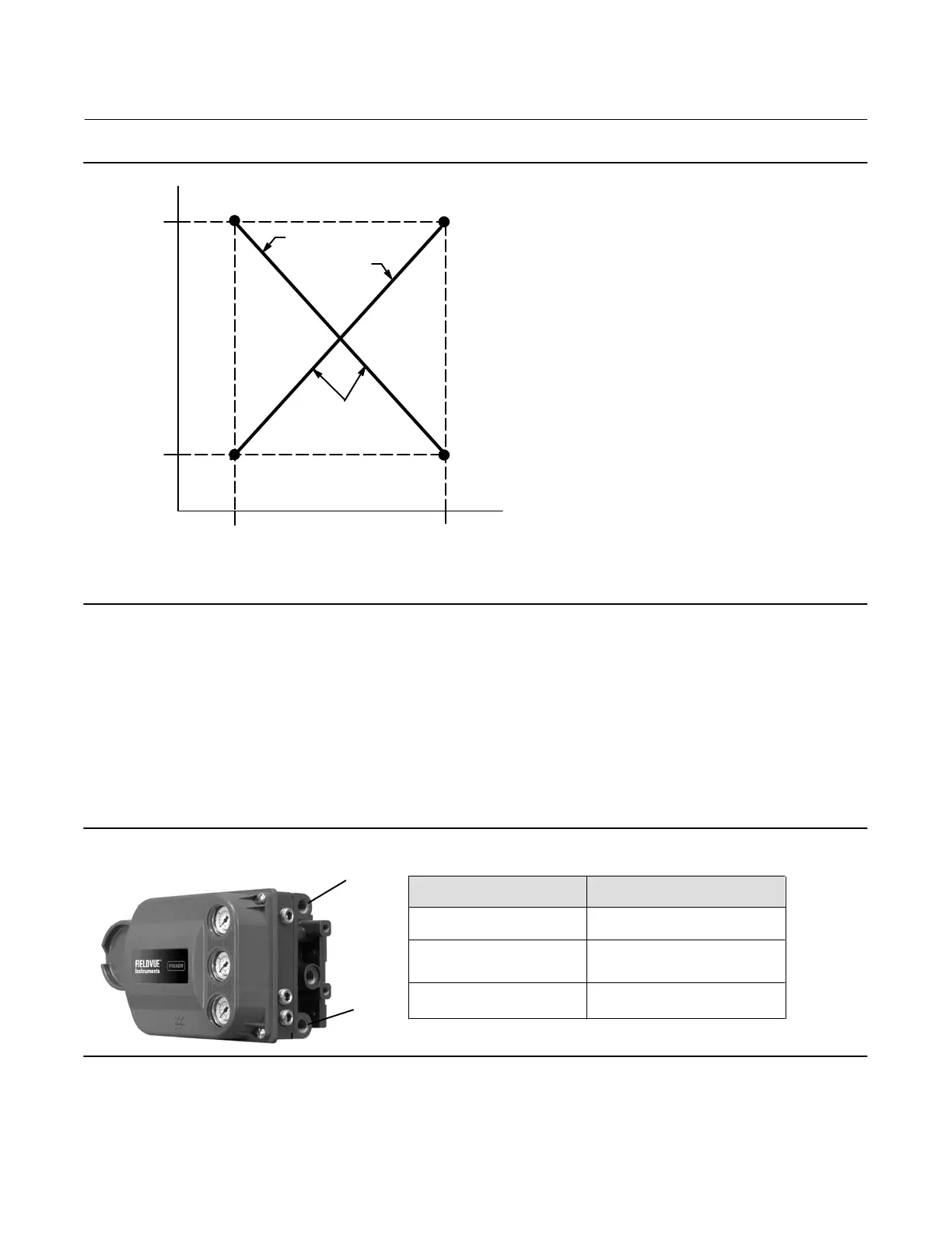
Figure 4‐5. Calibrated Travel to Analog Input Relationship
TRAVEL
RANGE
HIGH
TRAVEL
RANGE
LOW
THE SHAPE OF THESE LINES
DEPENDS ON THE INPUT
CHARACTERISTICS LINEAR
CHARACTERISTIC SHOWN
INPUT RANGE
LOW
INPUT RANGE
HIGH
ANALOG INPUT
mA OR % OF 4‐20 mA
CALIBRATED TRAVEL, %
A6531‐1
ZPC = CLOSED
ZPC = OPEN
NOTE:
ZPC = ZERO POWER CONDITION
Relay Type—There are three categories of relays that result in combinations from which to select.
Relay Type: The relay type is printed on the label affixed to the relay body.
A = double‐acting or single‐acting
B = single‐acting, reverse
C= single‐acting, direct
Special App: This is used in single‐acting applications where the “unused” output port is configured to read the
pressure downstream of a solenoid valve. See page 29 for additional information.
Lo Bleed: The label affixed to the relay body indicates whether it is a low bleed version.
Zero Power Condition—The position of the valve (open or closed) when the electrical power to the instrument is
removed. Zero Power Condition (ZPC) is determined by relay type, as shown in figure 4‐6.
Figure 4‐6. Zero Power Condition
A
B
Single‐Acting Direct (Relay C)
Port A pressure to zero.
Single‐Acting Reverse (Relay B)
Double‐Acting (Relay A)
Loss of Electrical Power
Port B pressure to full supply.
Port A pressure to zero.
Port B pressure to full supply.
Relay Type
Maximum Supply Pressure—Enter the maximum supply pressure in psi, bar, kPa, or kg/cm
2
, depending on what was
selected for pressure units.

 Loading...


