9-24
9-4-12 Data format
The data format of each piece of function code data of the inverter is defined here.
Prepare data according to the format numbered in the data format for each function code. (Refer to
section 5-1 Function Setting List and section 9-4-11 Function Code List for the data format.)
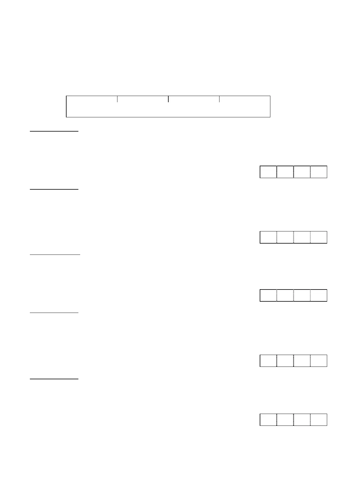
The data field of the transmission frame except for data format 10 consists of a 4-digit ASCII code
converted from a 4-digit hexadecimal data as shown in the figure below. For details of each format,
refer to the following data formats (1) through (11).
15
14
13
12
11
10
9
8
7
6
5
4
3
2
1
0
4-digit hexadecimal data => 4-digit ASCII code
(1) Data format 0
16-bit binary code, least increment 1, positive value only.
Example) In the case that F15: (frequency limiter, upper limit) = 60 Hz
60 x 1 = 60 (dec.) = 003C (hex.), hence: 003C ⇒
(2) Data format 1
16-bit binary code, least increment 1, positive/negative value
The negative value is expressed in 2's complement. -1 -> FFFF (hex.)
Example: In the case that F18: (bias frequency) = -20 Hz
-20 x 1 = -20 (dec.) = FFEC (hex.), hence: FFEC ⇒
(3) Data format 2
16-bit binary code, least increment 0.1, positive value only
Example) In the case that F17: (gain frequency setting signal) = 100.0%
100.0 x 10 = 1000 (dec.) = 03E8 (hex.), hence: 03E8 ⇒
(4) Data format 3
16-bit binary code, least increment 0.1, positive/negative value
The negative value is expressed in 2's complement. -1→ FFFF (hex.)
Example: In the case that C31: (analog input offset adjustment, terminal 12) = -5.0%
-5.0 × 10 = -50 (dec.) = FFCE (2's complement) ⇒
(5) Data format 4
16-bit binary code, least increment 0.01, positive value only
Example) In the case that C05: (multistep frequency 1) = 50.25 Hz
50.25 x 100 = 5025 (dec.) = 13A1 (hex.), hence: 13A1 ⇒
0 0 3 C
F F E C
0 3 E 8
F F C E
1 3 A 1