2-6
2-3-3 Connection of Control Terminal
Table 2-3-2 shows the functions of the control circuit terminals. The method of connecting control
function terminals varies according to the function setting. Refer to the connection method for the
function.
Table 2-3-2 Functions of control circuit terminals
Classifica-
tion
symbol
Terminal name Description of function
13
Potentiometer power
supply
+10 Vdc power supply for frequency setting POT.
(POT: 1 to 5 kohm).
12
Voltage input
(1) The frequency is set according to the external analog
input voltage command.
• 0 to +10 Vdc / 0 to 100%
• Reversible operation using +/- signal: 0 to +/-10 Vdc / 0
to 100%
• Inverse mode operation: +10 to 0 Vdc / 0 to 100%
(2) The PID control feedback signal is input.
* Input resistance: 22 kohm
C1
Current input (1) The frequency is set according to the analog input
current command.
• 4 to 20 mAdc / 0 to 100%
• Inverse mode operation: 20 to 4 mAdc / 0 to 100%
(2) The PID control feedback signal is input.
* Input resistance 250 ohm
Analog
input
11
Common Common for analog signals
FWD
Forward operation
command
Forward operation with FWD-P24 ON and deceleration
and stop with FWD-P24 OFF.
REV
Reverse operation
command
Reverse operation with REV-P24 ON and
deceleration-stop with REV-P24 OFF.
X1
Digital input 1
X2
Digital input 2
X3
Digital input 3
X4
Digital input 4
X5
Digital input 5
A coast-to-stop command from an external device,
external alarm, alarm reset, multi-step frequency selection
and other functions can be assigned to the X1 through X5
terminals. Refer to the terminal function E01 to 05 setting
method in section 5-2 Detail Description of Each
Function.
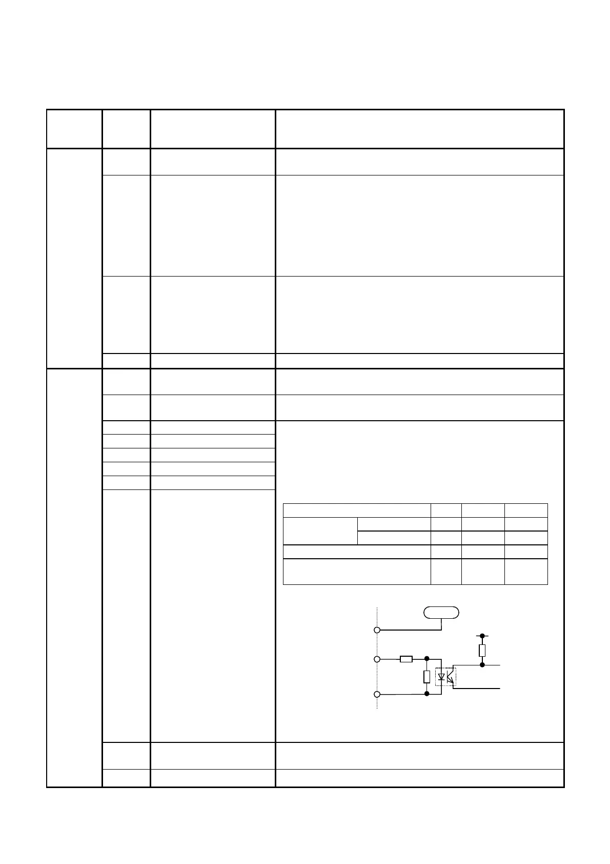
<Digital input circuit specification>
P24 Control unit
power supply
+24V DC power supply for control input.
Maximum output current : 50mA
Digital
input
CM
Common Common for digital input
FWD,REV,
CM
4.7kohm
P24
+24
Item
min.
typ. Max.
Level OFF 0V
- 2V Operation
voltage
Level ON 22V
24V 27V
Operation current at ON
- 4.2mA
6mA
Allowable leakage current at
OFF
- - 0.5mA

 Loading...


