12-1
12. Electromagnetic Compatibility (EMC) [Available only inverter for with CE mark ]
12-1General
In accordance with the provisions described in the European Commission Guidelines
Document on Council Directive 89/336/EEC,Fuji Electric Co., Ltd. has chosen to classify the
FVR-E11S range of inverters as "Complex Components".
Classification as a "Complex Components" allows a product to be treated as an "apparatus", and
thus permits compliance with the essential requirements of the EMC Directive to be demonstrated
to both an integrator of FVR inverters and to his customer or the installer and the user.
FVR inverters is supplied `CE-marked', signifying compliance with EC Directive 89/336/EEC
when fitted with specified filter units installed and earthed in accordance with this sheet.
This Specification requires the following performance criteria to be met.
EMC product standard EN61800-3/1997
Immunity : Second environment ( Industrial environment )
Emission : First environment ( Domestic environment )
Finally, it is customer’s responsibility to check whether the equipment conforms to EMC
directive.
12-2 Recommended Installation Instructions
It is necessary that to conformed to EMC Directive, these instructions must be followed.
Follow the usual safety procedures when working with electrical equipment. All electrical
connections to the filter, Inverter and motor must be made by a qualified electrical technician.
1) Use the correct filter according to Table 12-2-1.
2) Install the Inverter and filter in the electrically shielded metal wiring cabinet.
3) The back panel of the wiring cabinet of board should be prepared for the mounting
dimensions of the filter. Care should be taken to remove any paint etc. from the mounting
holes and face area of the panel. This will ensure the best possible earthing of the filter.
4) Use the screened cable for the control , motor and other main wiring which are connected to
the inverter, and these screens should be securely earthed.
5) It is important that all wire lengths are kept as short as possible and that incoming mains and
outgoing motor cables are kept well separated.
" To minimize the conducted radio disturbance in the power distribution system, the length
of the motor-cable should be as short as possible. "
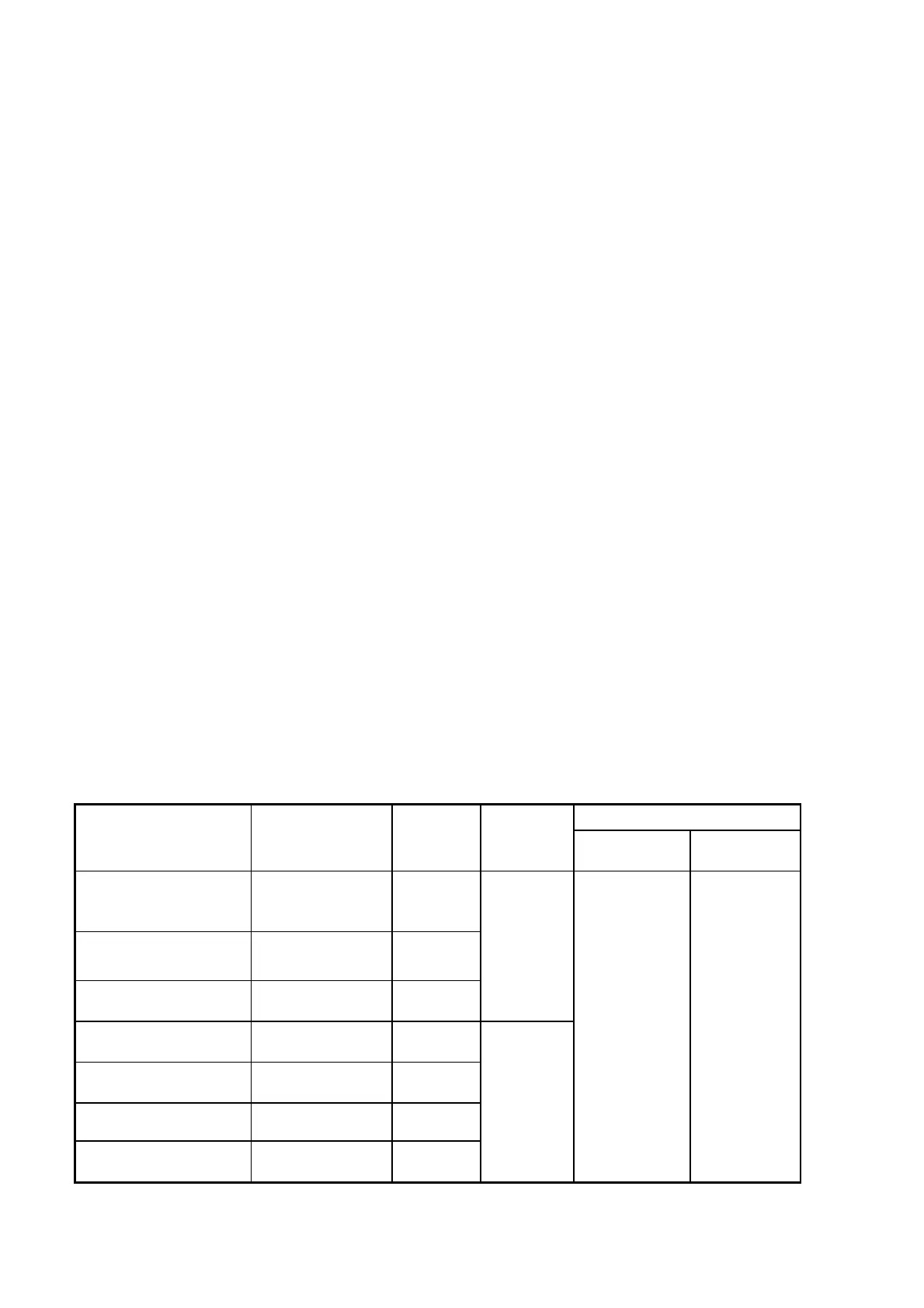
Table 12-2-1 RFI filters
Max. motor cable length
Applied
Inverter
Filter Type
Rated
Current
Max.
Rated
Voltage
EN55011
Class B
EN55011
Class A
FVR0.1E11S-7EN
FVR0.2E11S-7EN
FVR0.4E11S-7EN
EFL-0.4E11-7 6.5A
FVR0.75E11S-7EN EFL-0.75E11-7 18A
FVR1.5E11S-7EN
FVR2.2E11S-7EN
EFL-2.2E11-7 29A
1ph
240Vac
FVR0.4E11S-4EN
FVR0.75E11S-4EN
EFL-0.75E11-4 5A
FVR1.5E11S-4EN
FVR2.2E11S-4EN
EFL-2.2E11-4 10A
FVR4.0E11S-4EN EFL-4.0E11-4 15A
FVR5.5E11S-4EN
FVR7.5E11S-4EN
EFL-7.5E11-4 30A
3ph
480Vac
10m 50m
Note : For detail, refer to the instruction manual that came with the RFI filters.

 Loading...


