9-11
9-4 RS485 Communication
Remove the keypad panel of the inverter referring to section 1-3 (3) and use the connector having been
connected with the keypad panel to connect up to 31 inverters in a line to perform the following
operations.
• Frequency setting, forward/reverse rotation, stop, coast to stop, alarm reset and other
operations
• Monitoring of output frequency, output current, operation state, alarm description, and so
on
• Setting of function code data (function code data, command data and monitor data)
The transmission frame is character data having a fixed length of 16 bytes, so that development of
programs for the host controller is easy. The operation and frequency setting command requiring fast
speeds can be in a short frame for shorter communication time. The functions of the serial communication
connector are shown in Table 9-4-1.
Table 9-4-1 Functions of serial communication connector
Terminal
No.
Terminal
symbol
Name of terminal Specification
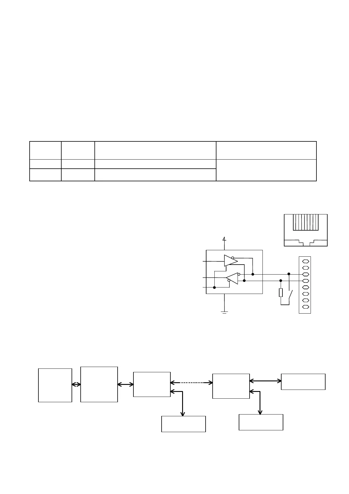
4 DX+ RS 485 communication signal (not inverse)
3 DX- RS485 communication signal (inverse)
Connection of serial
communication signal; compliance
with RS485
The leftmost terminal of the connector when viewed
from the front of the inverter is terminal 1.
Never connect the terminals other than the above
because signal cables used for the keypad panel are
connected. A terminator is built in the inverter.
Turn SW2 on (left side) below the serial
communication connector for the inverter connected
at the end of the cable to connect the terminator.
When you communicate more than one inverter,
use a branch adapter in the table 9-4-2 and connect
like Fig9-4-2.
Fig. 9-4-1 Equivalent circuit of RS485 interface
Personal
computer
Branch
adapter
Branch
adapter
RS485/
RS232C
converter
FVR-E11S
FVR-E11S
FVR-E11S
Remark)The branched cable length has to be 1m or less.
Terminattor in the branched inverter has to be OFF.(SW2 OFF)
Fig. 9-4-2 Communication method with more than one inverter
Remark
Remark
DI
RO
DE/RE
Connector for
Keypad panel
1
8
1
8

 Loading...


