2-11
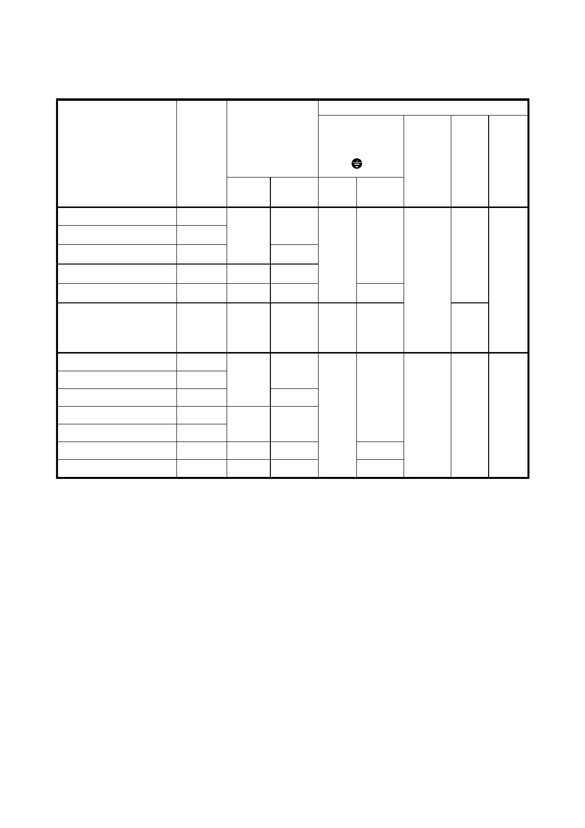
2-3-5 Applicable Devices and Cable Sizes for Main Circuit
Table 2-3-4 Selection of peripheral devices
Recommended wire size [mm
2
]
Molded case circuit
breaker (MCCB) or
earth leakage
circuit breaker
(ELCB)
*1
Rated current [A]
Input circuit
*2
[L1/R,L2/S,L3/T]
[L1/L, L2/N]
G
Inverter type
Nominal
applied
motor
[kW]
With
DCR
Without
reactor*
3
With
DCR
Without
reactor
*3
Output
circuit
*2
[U, V, W]
DCR
*2
circuit
[P1]
[P(+)]
DB
Control
wiring
FVR0. 1E11S-7EN
0.1
FVR0. 2E11S-7EN
0.2
6
FVR0. 4E11S-7EN
0.4
6
10
FVR0. 75E11S-7EN
0.75 10 16
2.5
FVR1. 5E11S-7EN
1.5 16 25
2.5
4
2.5
FVR2. 2E11S-7EN 2.2 25 32 4 6
2.5
2.5
(DB)
4
(Others)
0.5
FVR0. 4E11S-4EN
0.4
FVR0. 75E11S-4EN
0.75
6
FVR1. 5E11S-4EN
1.5
6
10
FVR2. 2E11S-4EN
2.2
FVR4. 0E11S-4EN
4.0
10 16
2.5
FVR5. 5E11S-4EN
5.5 16 25 4
FVR7. 5E11S-4EN
7.5 20 32
2.5
6
2.5 2.5 0.5
*1 The applicable frame and series of the model of the molded case circuit breaker (MCCB) and
earth leakage breaker (ELCB) vary according to the capacity of the transformer of the equipment.
For details of selection, refer to the concerning technical documents.
*2 The recommended cable size for the main circuit is the case for the use of the PVC cable at
ambient temperature 40 degree C specified in Appendix C of EN 60204
*3 The power supply impedance without a reactor is considered to be the equivalent of 0.1% of the
inverter capacity, with 10% current unbalance accompanied by the voltage unbalance.
*4 Up to crimp terminal (JIS C2805) RAV2-3.5 with max. 7.4 mm width (including tolerance) can be
used.
*5 Up to crimp terminal (JIS C2805) RAV5.5-4 with max. 9.8 mm width (including tolerance) can be
used.
*6 Use crimp terminals with an insulating cover.

 Loading...


