8-4
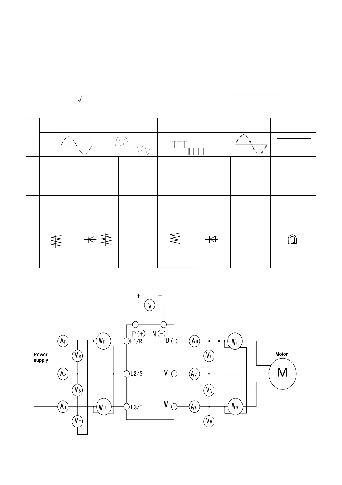
8-3 Measurement of Electrical Amounts in Main Circuit
Because the voltage and current of the power supply (input) of the main circuit of the inverter and the
output (motor) include harmonic components, the indicated value varies according to the type of the
meter. Use meters indicated in Table 8-3-1 when measuring with meters for commercial frequencies.
Marketed power factor meters measuring phase difference between the voltage and current cannot
measure the power factor. To obtain the power factor, measure the power, voltage and current on each
of the input and output sides and calculate in the following formula.
In case of Three-phase In case of Single-phase
Power factor
Electric power[W]
3 Voltage[V] Current[A]
100[%
=
× ×
× ]
Power factor
Electric power[W]
Voltage[V] Current[A]
100[%
=
×
× ]
Table 8-3-1 Meters for measurement of main circuit
Input (power supply) side Output (motor) side Link voltage
(P(+)-N(-))
Item
Voltage Current Voltage Current
Ammeter
A
R
,
S
,
T
Voltmeter
V
R
,
S
,
T
Wattmeter
W
R
,
S
,
T
Ammeter
A
U
,
V
,
W
Voltmeter
V
U
,
V
,
W
Wattmeter
W
U
,
V
,
W
DC voltmeter
V
Moving iron
type
Rectifier or
moving iron
type
Digital
power
meter
Moving iron
type
Rectifier
type
Digital
power meter
Moving coil
type
Note) When the output voltage is measured by a rectifier type, an error may be included. To increase the
accuracy, use a digital AC power meter.
Fig. 8-3-1
Connection of meters
(L1/L)
(L2/N)

 Loading...


