6. SYSTEM DESIGN
CHECK RUN CHECK ITEMS AND PROCEDURE6-2.
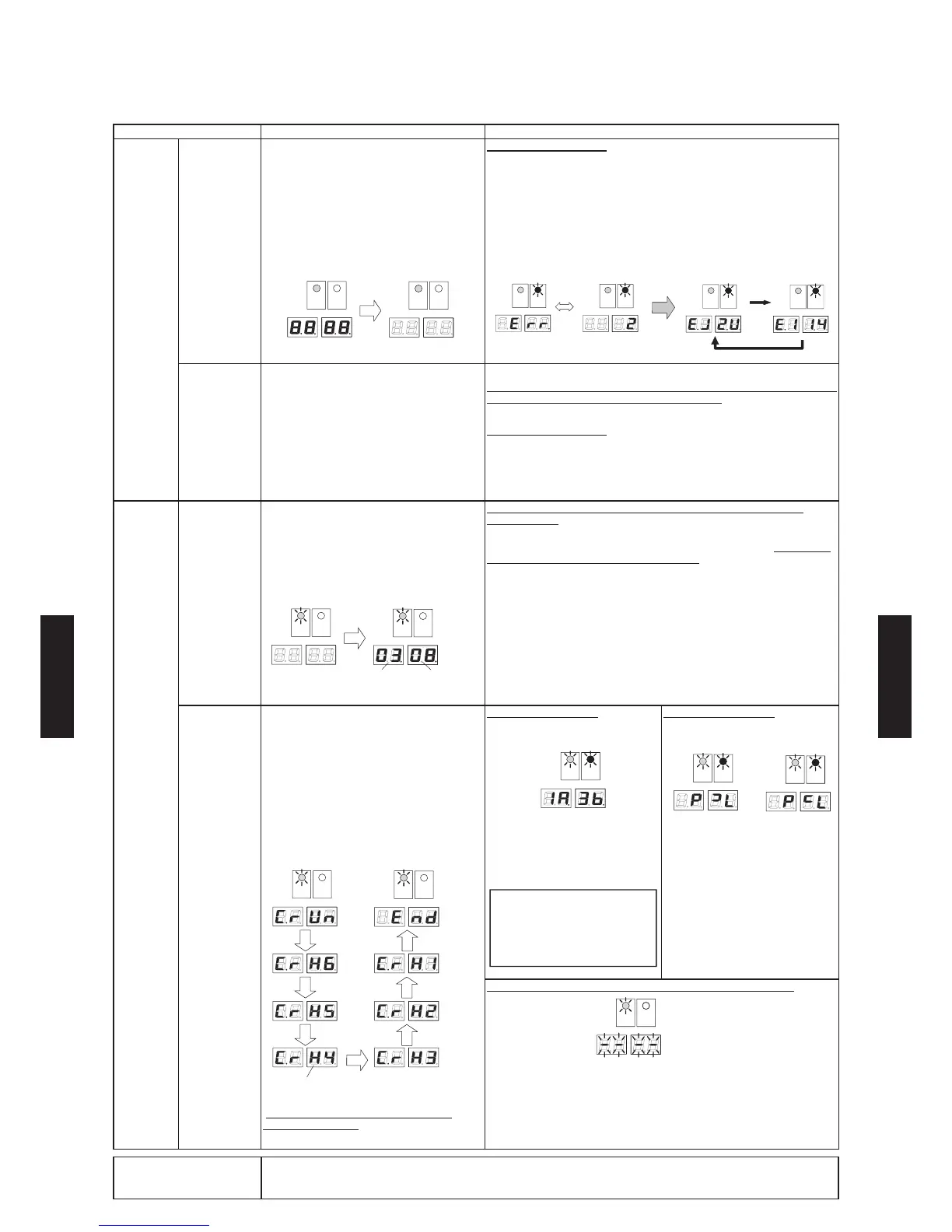
Use the following procedure to perform the Check run.
Check Item Procedure When an Error Occurs
1. Turn on
power
1.1 Check
communi-
cations
he power is on to the outdoor unit
connected branch boxes, and indoor units.
utoatica deterined ater the power is
turned on.
he deterination taes about inutes.
(During this time, the outdoor unit 7 seg.
displays are all lit.)
he deterination is pass i a seg. dispas
of the outdoor unit turn off.
LED961 LED962
LED981
POWER
MODE
LED982
ERROR
LED961 LED962
LED981
POWER
MODE
LED982
ERROR
<All lit state> <All off state>
When an error occurred
he nuber o error is autoatica dispaed.
he error codes can be checed using the button.
ter checing the error code turn o the power and resoe the probe.
[Ex] When a branch box error and serial signal error occurred (error during
operation).
LED961 LED962
LED981
POWER
MODE
LED982
ERROR
LED961 LED962
LED981
POWER
MODE
LED982
ERROR
LED961 LED962
LED981
POWER
MODE
LED982
ERROR
LED961 LED962
LED981
POWER
MODE
LED982
ERROR
<Displays the number of error> <Displays error code>
Press ENTER
button
The error code switches each time
the SELECT button is pressed.
1.2 Compressor
preheat
operation
he power is on to the outdoor unit
connected branch boxes, and indoor units.
ter the power is turned on preheating o the
compressor starts automatically. (Conduct
preheating for at least 12 hours.)
onr that a the outdoor unit seg.
displays are off. (If there is an indoor unit,
branch box, or outdoor unit error, preheating
of the compressor will not be performed.)
[Caution]
If the power has been off for more than 6 hours, preheat the compressor for
at least 12 hours before conducting the Check run.
When an error occurred
he nuber o error is autoatica dispaed.
he error codes can be checed using the button.
ter checing the error code turn o the power and resoe the probe.
urn the power on again.
2. Check run 2.1 Check the
number of
connected
units
ontinue pressing the button or
more than 3 seconds to begin checking the
number of connected units.
ter the nuber o connected units is shown
in the outdoor unit 7 seg. display, check if the
number of installed branch boxes and indoor
units has been detected correctly.
LED961 LED962
LED981
POWER
MODE
LED982
ERROR
LED961 LED962
LED981
POWER
MODE
LED982
ERROR
<All off state> <Number of units display>
Number of
Branch boxes
Number of
Indoor units
If the number of displayed units does not match the number of
installed units
If the number of units displayed by the outdoor unit indicators does not
match the number of installed branch boxes and indoor units, recheck the
wiring work and perform the Check run again.
2.2 Check
connected
positions
ontinue pressing the button or
more than 3 seconds to begin operation to
check the connected positions.
he deterination taes about hour. uring
this time the outdoor unit 7 seg. display will
show "C.rUn".)
he deterination is pass when nd is
displayed on the outdoor unit 7 seg. display.
Ex) mode: HEAT, 6 indoor units
H: HEAT, C: COOL
LED961 LED962
LED981
POWER
MODE
LED982
ERROR
LED961 LED962
LED981
POWER
MODE
LED982
ERROR
<Check run start>
<Check run
ends normally>
Check run has been completed. Please
conduct the test run.
Wiring Mistake Case 1
Connection destination does not
match
LED961 LED962
LED981
POWER
MODE
LED982
ERROR
[Display Explanation]
The wire connected to Terminal A
of Branch box1 (left 2-digit) must be
rewired to Terminal B of Branch box
3 (right 2-digit).
[Caution]
The displayed wiring mistake
positions are displayed by the
indicators in order. Make a note of
all of them before turning off the
power and rewiring.
Wiring Mistake Case 2
Problem with the wiring or piping
connection
 Loading...