6. SYSTEM DESIGN
FUNCTION SETTING5.
OUTDOOR UNIT5-1.
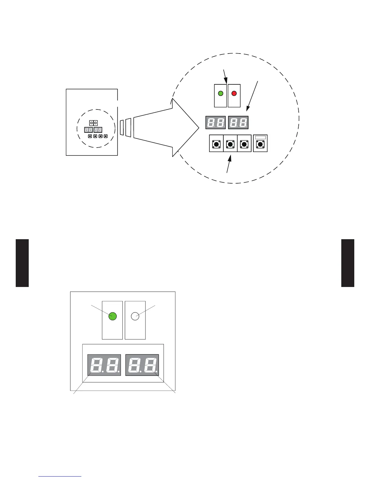
SWITCH POSITION
LED981
POWER
/ MODE
LED982
ERROR
LED961 LED962
MODE /
EXIT
SW931
SELECT
SW932
ENTER
SW933
CHECK
SW934
Outdoor unit printed circuit board
LED lamp
7 Segment
LED Lamp
Push button
Set the functions of the outdoor unit with the push buttons (SW931, SW932 and SW933) while
observing the 7-segment LED lamps (LED961 and LED962) on the printed circuit board.
PREPARATION
Be sure to check that the operation of the outdoor unit has stopped (be sure to stop the 1)
operation if it is still running), and turn off the power.
Remove the front panel of the outdoor unit, and remove the lid of the electrical component box 2)
in order to expose the printed circuit board.
Turn on the power of the outdoor unit.3)
As shown in the figure below, make sure that the POWER/MODE indicator lamp (LED981) is on
and the ERROR indicator lamp (LED982) is off.
LED981
POWER
/ MODE
LED982
ERROR
LED961 LED962
When the system is normal
(Off)
(On)
(Off)
(Off)
the indicator ap ashes it indicates that an error has occurred. hec
wiring and power supply. After making sure that the ERROR indicator lamp (LED982) has turned
off, proceed to the next step.
- (06 - 52) -
SYSTEM
DESIGN
SYSTEM
DESIGN
 Loading...