6. MAINTENANCE, TROUBLESHOOTING
6-9
5. Press the F1 key three times to show the results for antenna test.
You can save a screenshot to a SD Card if there is a SD Card inserted into the
Processor Unit. Press the F4 key three times to save a screenshot.
6. Press the F1 key to close the test results and complete the test.
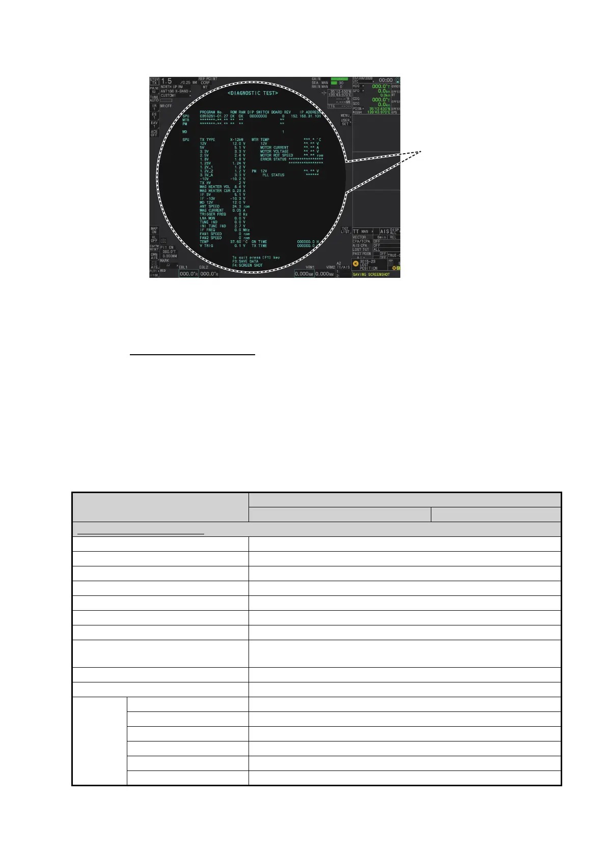
Diagnostic test results
The following table lists each test result along with the normal value range for each
item. "OK" appears for normal operation. If "NG" (No Good) appears, corresponding
components may be defective.
Also, if a connected fan or PCB shows the check results as asterisks, it is an indication
that the fan or PCB has failed, or is disconnected.
If there are any components which are suspected to be defective, or any test does not
complete satisfactorily, consult your dealer for advice.
Tested item
Normal value or Description
Magnetron Radar Solid State Radar
MAIN (Processor Unit) test
[PROGRAM No.] Shows the program version number.
[ROM] OK
[RAM] OK
[DIP SWITCH] Shows the DIP SWITCH settings.
[IP ADDRESS] Shows the IP address for the Processor Unit.
[SD CARD] OK
[SD CARD RP] (Not currently used)
[HSC] Shown only for systems with the optional High Speed Conver-
sion kit.
[RMS] Shown only when Remote Maintenance Service is enabled.
[ICE] Shown only when Ice Mode is enabled.
[MAIN] [12V] 10.8 to 13.2 V
[5V] 4.7 to 5.3 V
[3.3V] 3.0 to 3.6 V
[2.5V] 2.3 to 2.7 V
[1.8V] 1.6 to 2.0 V
[1.25V] 1.13 to 1.38 V
Antenna diagnostic test
results appear here.
ALERT HANDLING IS DISABLED


 Loading...