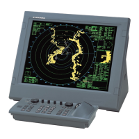
1. OPERATIONAL OVERVIEW
1-8
11 [TRIAL MANEUVERS] box • Activates/deactivates trial maneuvers.
• Sets up trial maneuver parameters.
12 [ACQUISITION ZONE] box • Adjust acquisition zone settings for target alarms.
• Toggle between sentry zone and acquisition zone alert
modes.
13 [VRM] box • Activate/deactivate the VRM (Variable Range Marker).
• Adjust the active (selected) VRM.
• Shows VRM range and TTG.
14 [EBL] box • Activate/deactivate the EBL (Electronic Bearing Line).
• Adjust the active (selected) EBL.
• Shows EBL bearing.
15 [MAP MARK] box • Selects a map mark to use.
• Inscribes the selected map mark.
16 [PI Lines] box • Selects PI line set to use.
• Shows/hides the selected PI lines.
• Shows the angle, reference and range interval for the
PI lines.
17 [TARGET ANALYZER] indica-
tion
Shows the target analyzer function’s ON/OFF status.
Note: Appears only for B/W-types.
18 [NOISE REJECTOR] indication Shows the noise rejector function’s ON/OFF status.
19 [TUNING LEVEL] bar • Shows the level of tuning in use. See section 1.17.
• Adjusts the tuning (manual only). See section 1.17.3.
Note: The [TUNING LEVEL] bar is not shown for solid
state radars.
20 [PICTURE] box • Selects a preset custom display.
• Right-click to open the [CUSTOMIZED ECHO] menu.
21 [ANTENNA SELECTION] box • Selects the antenna to use for radar images.
• Right-click to open the [SELECT ANTENNA] menu.
22 [CONTROL] box Indicates which Dual Radar image is currently selected.
• "M": Master. Operations and settings are applied to the
Main (Master) radar image.
• "S": Slave. Operations and settings are applied to the
Sub (Slave) radar image.
Note: Appears only for A/B-types when the dual radar
function is enabled at installation and the connected ra-
dar is turned on.
23 [PRESENTATION MODE] box Change the presentation (orientation) mode for the radar
images.
24 [DROP MARK] box Shows the bearing and range to the drop mark(s).
25 Screenshot button Saves a screenshot of the entire displayed area.
Note: Requires SD card to be inserted in the Processor
Unit. Shown in gray and not selectable if no SD card is in-
serted.
26 Stabilization mode button Change the stabilization mode (WT (sea stabilization) or
BT (ground stabilization)).
No. Name Description

 Loading...


