1.
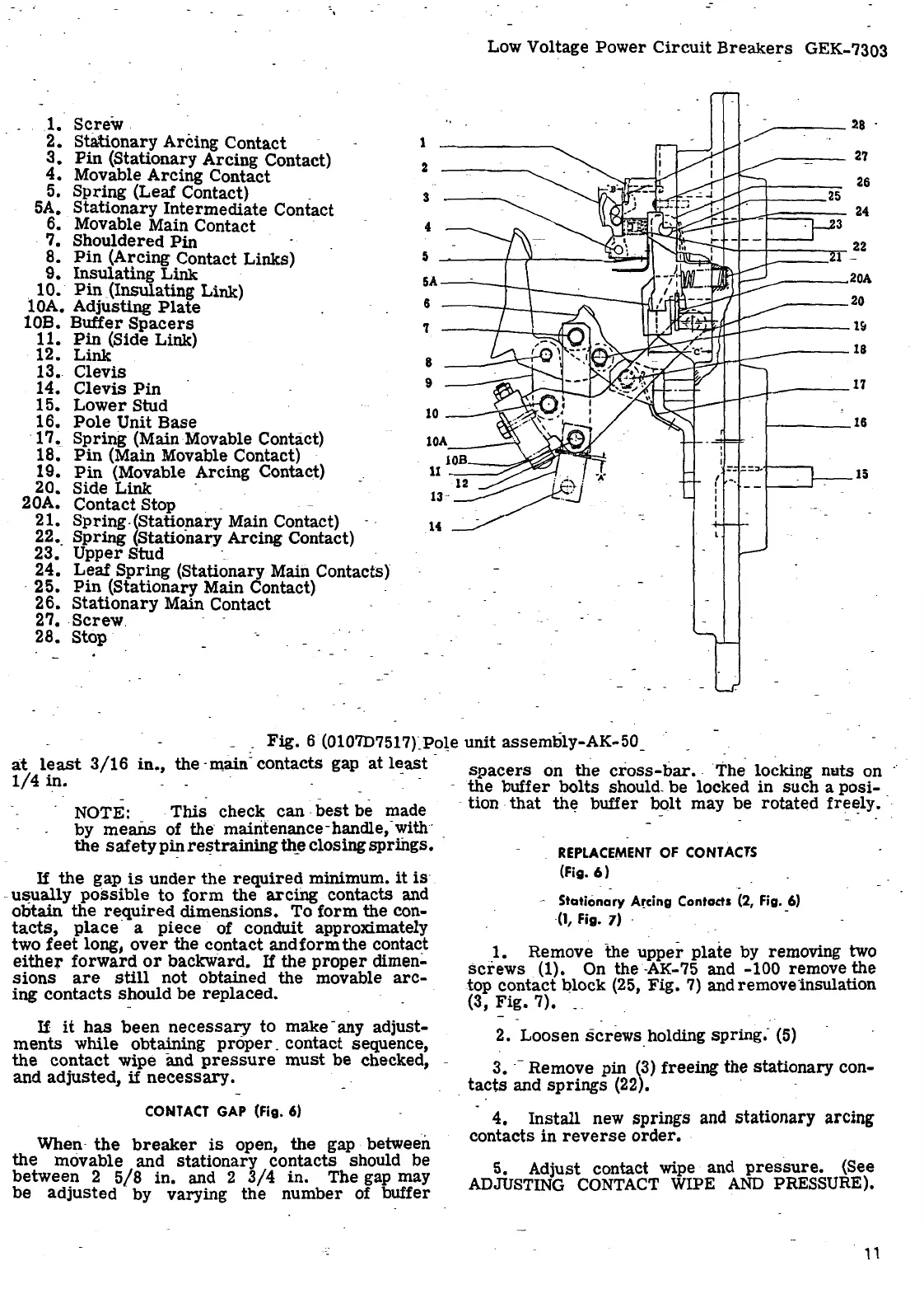
Screw
.
2.
Stationary
Arcing Contact -
3.
Pin
(Stationary
Arcing
Contact)
4.
Movable
Arcing
Contact
5.
Spring
(Leaf Contact) _
5A.
Stationary
Intermediate
Contact
6. Movable Main Contact ·
.
7.
Shouldered
Pin
1
2
3
4
Low Voltage
Power
Circuit
Breake~s
GEK-7303
-
28
·
~
---------
27
26
8.
Pin
(Arcing Contact Links)
5
~---t-..,,._---.....::,aa-...,
•--r--+---+----...--
22
.J.------~l
-
9.
Insulating
Link ·
.
10.
Pin
(Insulating Link)
lOA. Adjusting
Plate
5A-~--t---\----~-
______
20A
10B.
Buffer
Spacers
11.
Pin
(Side Link)
12.
Link
13.
Clevis
14.
Clevis
Pin
6
'l
8
9
___
20
~~f/r:J__..-------1~
----18
15.
Lower
Stud
16.
Pole
Unit
Base
10
-----
1-----16
·
17.
Spring
(Main Movable Contact)
18.
Pin
(Main Movable Contact) ·
lOA
____
,
19.
Pin
(Movable Arcing Contact)
20. Side
Link
- _
20A.
Contact
Stop . - · -
21.
Spring
-(Statio:f1ar.y Main Contact) - -
22 •.
Spring
(Stationary Arcing Contact)
23.
Upper
Stud -_ ·
24.
Leaf
Spring
(Stationary Main Contacts)
·
25.
Pin
(Stationary Main Contact) -
26.
Stationary
Main Contact
27 • .
screw
.
28.
Stop
=-
.:=.;,,.-i----,
{ -.
I
I
15
.
Fig.
6 (0107D7517rPote
unit
assembly-AK-50
_
a:t
least
3/16
1/4
in.
in.,
the ·main: contacts gap
at
l~ast
-
spacers
on
the
cross-bar
• . The ~ocking nuts
<?D
-
the
buffer
bolts
should.
be
locked m
such
a pos1-
- -
NOTE: -
This
check
can
.
best
be made
by
means
of the
m~~tenance
-
h~dle,-~ith
- _
the
safety
pin
rel?trammg
th_e
closing
springs.
If
the
gap
is
under
the
required
minimum.
it
is
-
usually
possible
to
form
the
arcing
contacts and
obtain
the
re_quired
dimensions.
'FO
form
~e
con-
tacts,
place
a
piece
of conchnt approximately
two
feet
long,
over
the
contact
and
form
the contact
either
forward
or
backward.
If
the
proper
dimen-
sions
-
are
still
not
obtained
the
movable
arc-
ing
contacts
should
be
replaced.
If
it
has
been
necessary
to
make -any adjust-
ments
while obtaining
proper
_
contact
sequence,
the
contact
wipe and
pressure
must
be
checked, -
and
adjusted,
if
necessary.
CONTACT
GAP
(Fig.
6)
When·
the
breaker
is
open,
the
gap -between
the
movable and
stationary
contacts
should be
between
2
5/8
in.
and 2
3/4
in.
The gap may
be
adjusted
·
by
varying
the
number
of buffer
- tion
that
th~ buffer
bolt
may
be
rotated
fre~ly.
REPLACEMENT
OF
CONTACTS
(Fig.
6)
- .
- Stationary
A~cing
Contads (2,
Fig.
_6)
(1,
Fig.
7) -
1. Remove
the
upper
plate
by removing two
screws
. (1). On the -AK-75 and -100 r~move
~e
.top
contact
Qlock (25,
Fig.
7)
and remove insulation
(3,
Fig.
7).
__
- .
2.
Loosen
screws
holding
spring.
- (5)
3 • . - Remove pin
(3)
freeing the
stationary
con-
.
tacts
and
springs
(22). · ·
4.
Install
new springs and
stationary
arcing
contacts
in
reverse
order.
·
5. Adjust contact wipe and
pressure.
(See
ADJUSTING
CONTACT
WIPE
AND
PRESSURE).
,,
 Loading...


