Low Voltage Power Circuit
Breakers
GEK-7303
. . .
..
SERIES OVERCU~RENT
TRIPPING
DEVICE EC-2~
EC-2A,
AK-SO
The
Type
EC-2,
EC-2A, (see
Fig.
29)
over-
case, which
~ay
be
taxen
off
without disturbing
current
tripping device
is
available in
three
forms: the
trip
unit
itself.
·
1.
Dual
overcurrent
trip,
with long-
time
delay
and high-
set
instantaneous tripping.
2.
Low-set
instantaneous tripping.
S.
High-set
instantaneous tripping.
The
dual
trip
has
adjustable long-time and
instantaneous 12ick-up settings and adju~table time
settings
. Both ·
forms
of instantaneous
trip
have~
adjustable pick-up settings.
LONG
TIME-DELAY
AND
HIGH-SET
INSTANTANEOUS
TRIPPING
(Fig.
29)
.
I
By means of the adjustment knob (3), whicb
can
be
manipulated by hand, the
current
pick-up
point can
be
varied
from
80
to 160
percent
of the
series
coil
rating.
The indicator and a calibration
I
plate (2) on the
front
of the
case
provide a means
of indicating the pick-up point setting
in
terms
of
percentage of coil rating. The calibration
plate
is
indexed
at
. percentage settings of 80, 100, 120,
1140, and 160.
· As
in
the
case
· of the EC-1 over-
current
trip,
I
the
long-time
delay tripping feature
can
be
supplied
with any one of
three
time-current
characteristics
which
correspond
to the
NEMA
standards
max-
imum,
intermediate
and minimum
long-time
delay
I
operating bands. These
are
identified
as
lA,
lB and 1 C
characteristics,
respectively.
Ap-
proximate tripping
time
for
. each of
these,
in the
same
order
are
30, 15, and 5
seconds
at
600
I
percent of the pick
-u
p value
of
current.
(See
time-current
characteristic
curves,
Fig.
42).
The tripping
time
may be
varied
within the
I
limits shown on the
characteristic
curves
by
turn-
ing
the
time
adjustment
screw
(4).
Turning
in
a
clockwise
direction
in(?reases· the tripping
time;
counterclockwise
O).Otion
decreases
it.
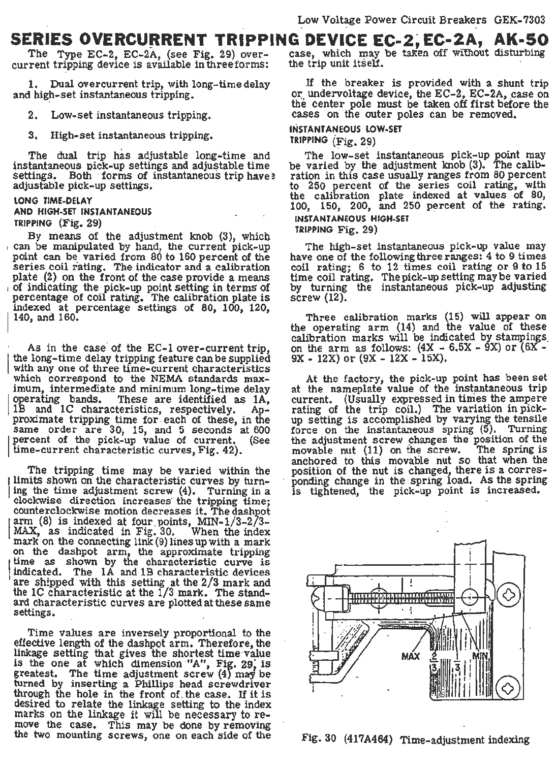
The
dashJ?Ot
I
arm
(8)
is
index~d
at
four. points,
MIN
-
1/3-2/3-
MAX,
.
as
_indicated
in
Fig. 30. When the index
mark on
the
connecting
link(9)linesupwith
a
mark
on
the dashpot
arm,
the approximate tripping
I
time
as
shown by the
characteristic
curve
is
indicated.
The
lA
and
lB
characteristic
devices
are
shipped with
this
setting
at
the
2/3
mark
and
the 1 C
characteristic
at
the 1/3
mark.
The
stand-
ard
characteristic
curves
are
plotted
at
these
same
settings.
Time
values
are
inversely
proportional
to
the
effective
length
of the dashpot
arm.
Therefore,
the
linkage
setting
that
gives the
shortest
time
·value
is
the one
at
which dimension ·
11
A",
Fig.
29;
is
greatest.
The
time
adjustment
screw
(4) may be
turned by
inserting
a Phillips head
screwdriver
through
the
hole
in
the
front
of-the
case.
If
it
is
desired to
relate
the linkage setting
to
the
index
marks on the linkage
it
will be
necessary
to
re-
move
the
case.
This
may be done by removing
the
two mounting
screws,
one on each
side
of the
If the
breaker
is
provided with a shunt
trip
ox:
. undervoltage device, the EC-
2,
EC-2A, .
case
on
the
center
pole
must
be taken off
first
before the
cases
on the ou
ter
poles
can
be
removed.
INSTANTANEOUS
LOW
-SE
T
TRIPPING
{Fig.
2~)
.·
The l
ow-set
instantaneous pick-up point may
be
varied
by the adjustment knob (3).
The
calib-
ration
in
this
case
usually
ranges
from
80
percent
to
250
percent
of the
series
coil
rating, with
the
calibration
plate indexed
at
values of 80,
100, 150, 200, and 250 p~rcent of the rating.
INS
TANTANEOUS
HIGH-SET
TR
IPPING
Fig.
29)
The high-.set instantaneous pick
-u
p value may
have one of the following
three
ranges:
4
to
9
times
coil rating; 6
to
12
times
coil rating
or
9
to
15
time
coil rating. The pick-up setting may be
varied
by turning the instantaneous pick-up adjusting
screw
(12).
Three
calibration
marks (15) will
appear
on
the operating
arm
(14)
and the value of
these
calibration
marks
will be indicated by stampings.
on the
arm
as
follows:
(4X
- 6.5X -
9X)
or
(6X
-
9X
- 12X)
or
(9X
-
12X
-
15X)
. .
At the ·factory, the
pick-:-up
point
has
been
set
at
the nameplate value of the
inst~taneous
trip
current.
(Usually expressed in
times
the
ampere
rating of the
trip
coil.) The
variation
in
pick-
up
setting
is
accomplished by varying the
tensile
force
on the instantaneous
spring
(5). Turning
the adjustment
screw
changes the position . of the
movable nut (11) on the
screw.
The
spring
is
anchored
to
this
movatile nut
so
that when the
position of the nut
is
changed,
there
is
a
corres-
- ponding change
in
the spriI?g load. As the
spring
is
tightened, the pick-up point
is
increased.
Fig. 30 (417A464) Time-adjustment indexing
 Loading...


