GEK-7303 Low Voltage
Power
Circuit
.
Breakers
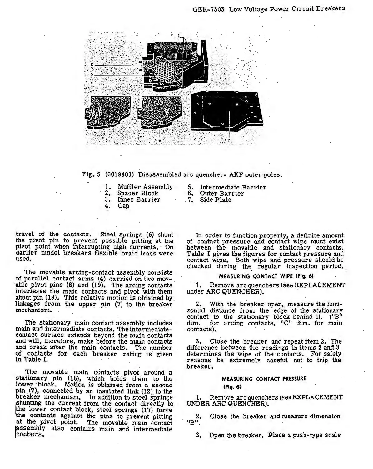
Fig.
5 (8019408) Disassembled
arc
quencher- AKF
outer
poles.
1. Muffler Assembly
2.
Spacer
Block
3.
Inner
Barrier
4. Cap
travel
· of · the
contacts.
Steel
springs
(5)
shunt
the pivot pin to
pr
_event possible pitting
at
the
pivot point when interrupting high
currents.
·
On
earlier
model
breakers
flexible
braid
leads
were
used.
rhe
movable ~rcing-contact a~sembly consists
of
parallel
contact
arms
(4)
carried
on two mov-
·able pivot
pins
(8)
and (19). The
arcing
con.tacts
interleave the main · contacts and pivot with them
about pin (19).
This
relative
motion
is
obtained by.
linkages
from
the
upper
pin
(7)
to the
breaker
mechanism. . . ·
Th·e
stationary
main contact
assembly
includes
main and
intermediate
contacts. The
intermediate-
contact
surface
extends beyond the main contacts
and will,
therefore,
make
before
the main contacts
and
break
after
the main contacts. The number
of contacts
for
each
breaker
rating
is
· given
in
Table
I.
The movable main contacts pivof around a
stationary
pin (18), which holds
them
. to the
lower
·block. Motion
is
obtained
from
a second
pin
.(7), connected by an insulated
link
(12). to tl\e
breaker
mechanism.
In
addition to
ste
·
e1
springs
shunting
the
current
from the contact ·
directly
to
!the
lower
contact block,
steer
springs
(17)
force
liiie
con~cts
ag~nst
the pins to prevent pitting
at
the
pivot
pomt. The movable main contact
jassembly
also
contains main and intermediate
!contacts.
5. Intermediate
Barrier
6.
Outer
Barrier
. 7. Side
Plate
In
order
to function
properly,
a definite amount
of contact
pressure
and contact wipe must
exist
between . the movable and
stationary
contacts.
Table I gives the
figures
for
contact
pressure
and
contact wipe. Both wipe and
pressure
should be
cpecked during the_
regular
inspection period.
-:
MEASURING
CONTACT
WIPE
(fig. 6)
· 1. Remove
arc
quenchers
(see
REPLACEMENT
under
ARC
QUENCHER). .
2. With the
breaker
open,
measure
the hori-
zontal distance
from
. the edge of the stationary
contact to the
stationary
block behind
it.
('.'B"
dim.
for
arcing
contacts, "C" dim.
for
.main
contacts). ·
3. Clo.
se
the
breaker
and repeat
item
2. The
difference between the readings in items 2 and 3
determines
the wipe of the · contacts.
For
safety
reasons
be extremely careful not to trip the
breaker.
· . ·
MEASURING
CONTACT
PRESSURE
(Fig.
6)
1. Remove
arc
quenchers (see REPLACEMENT
UNDER
ARC
QUENCHER).
2. Close the
breaker
and measure dimension
"B".
3.
Open the breaker.
Place
a push-type
scale
 Loading...


