GEK-7303
Low
· Voltage Power Circuit Breakers
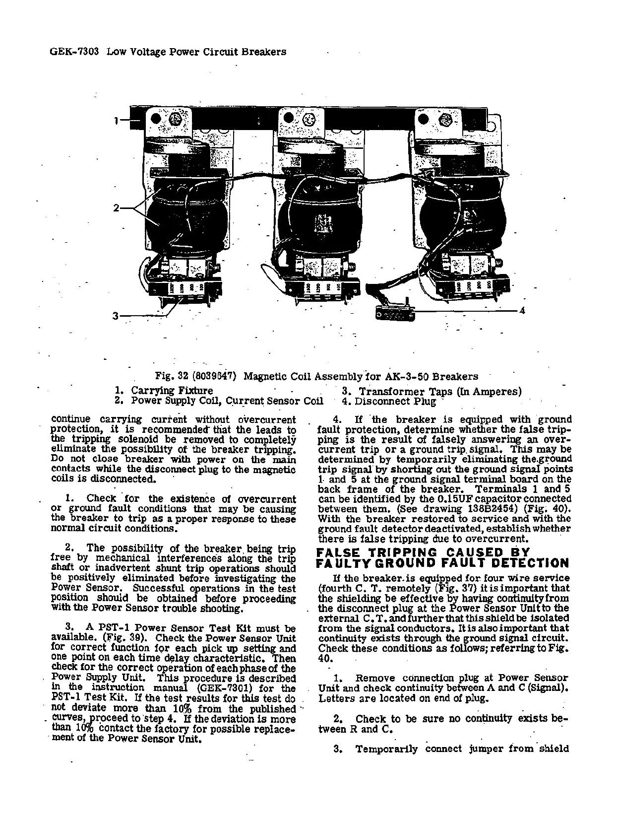
Fig. 3·2
(8039647)
Magnetic Coil Assembly.
for
AK-3-50
Breakers
1. Carrying Fixture · · .. . 3.
Transformer
Taps (In Amperes)
2. Power Supply Coil, C.
uz:ren~
Sensor Coil · 4. Disconnect
Plug
·· . · .
continue carrying current without overcurrent 4..
If
·the
breaker
is
equipped with ·ground
protection,
it
is
recommended' that. the leads to fault protection, determine whether the
false
trip
-
the tripping solenoid be removed to completely ping
is
the
result
of falsely answering
an
over-
eliminate the possibility of the breaker tripping.
current
trip
or
a ground
trip
. signal. This may
be
Do
not close
breaker
with power
on
the main determined by
temporarily
eliminating the.g~ound
contacts while the disconnect plug to the magnetic
trip
signal· by shorting out the ground signal points
coils
is
disconnected. · l and 5
at
the ground signal terminal board on the
1. Check · for the existence of overcurrent
or
ground
fa
ult conditions that may
be
causing
the breaker to
trip
as
a proper response to these
normal circuit conditions.
2. The possibility of the breaker. being
trip
free by mechanical interferences along the
trip
shaft
or
inadvertent shunt trip operations should
be positively eliminated before investigating the
Power Sensor. Successful operations in the
test
p~sition should be obtained before proceeding
with the Power Sensor trouble shooting. ·
3. A PST-1 Power Sensor
Test
Kit must
be
· available.
(rig.
39). Check the -Power Sensor Unit
for
correct
function
f<;>r
each pick up setting and
one
point on each time d~lay characteristic. Then .
check for the
correct
operation of each phase of the
Power Supply Unit. This procedure
is
described
in
the instruction manual
(GEK-7301)
for the
PST-1
Test
Kit.
If
the
test
results for this
test
do
.
: not deviate more than
10%
froin the published
··
·
.
curves~__pz:oceed
to ·step
4-.
If the deviation
is
more
than
10%
contact the factory for possible replace-
.
ment
of the Power Sensor Unit.
back
frame
of the
breaker.
Terminals 1 and 5
can
be
identified by the 0.15UF capacitor connected
between them. (See drawing 138B2454)
(Fig~
40).
With the
breaker
restored
to
service
and with the
ground fault
detector
deactivated, establish whether
there
is
false
tripping due to overcurrent. ·
FALSE
TRIPPING
CAUS.ED
BY
FAULTY
GROUND
FAULT
DETECTION
If
the
breaker.
is
equipped for. four wire
service
(fourth C. T. remotely (Fig. 37)
itisimportant
that
the shielding
be
effective by having continuityfrom
the disconnect plug
at
the Power Sensor Unit to the
external
C.
T.
and
further
that this shield be isolated
from
the signal conductors.
It
is
also important that
continuity
exists
through the ground signal circuit.
Check
these
conditions
as
follows;
referring
to
Fig.
40.
1.
Remove connection plug at Power Sensor
Unit and check continuity between A and C (Signal).
Letters
are
located
on
end of plug.
. .
2. Check to
be
sure
no
conµnuity
exists
be-
tween
Rand
C. ·
3.
Temporarily connect jumper
from
. shield
 Loading...


