Low Voltage
Power
Circuit
Breakers
GEK-7303
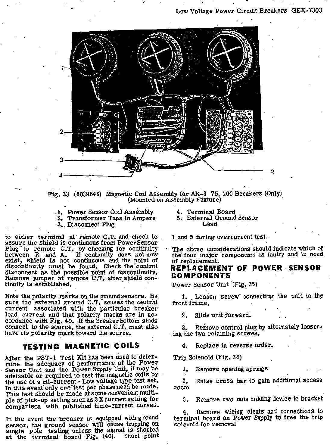
Fig.
33
(8039646) Magnetic Coil Assembly
for
AK-3 75, 100
Breakers
(Only)
· (Mounted on Assembly
Fixture)
·
.1 •.
Power
Sensor Coil Assembly
2.
Transformer
Taps in Ampere
3 •. Disconnect Plug
to
either
terminal
·
at
· remote C. T. and check to
a
ss
ure
the
shield
is
continuous from Power
Sensor
Plug
..
to
remote
C.T.
by checking
for
continuity
between R and A.
If
continuity does not
now
exist,
shield
is
not continuous and the point of
discontinuity
must
be
found~
Check the control
disconnect
as
the
possible
point of discontinuity.
Remove.
jumper
at
remote
C.T.
after
_shield
c;:on:.
tinuity
is
establi~~ed. · ·
Note the
po
_
larity
marks
on the grounc!_sensors.
~e
sure
the
external
ground C.
T.
senses
the
neutral
current
associated
with the
particular
breaker
load
current
and
that
polarity
marks
are
in
ac
-
cordance with
Fig.
40.
If
the breakerbottom
studs
connect to the
source,
the external C.T.
must
also
· have
its
polarity
~,;irk toward the source.
TESTI
N~ _
MAGNET
IC
COILS
After
the
PST-1
Test
Kit
has
been used to
deter-
mine
the
adequacy
of
perf~rmance o!
t1?e
Power
.
Sensor
Unit and the .
Power
SUpply
Unit,
it
may
be
advisable
or
required
to
test
the magnetic coils by
the
use
of a
Hi-current-
Low voltage type
test
set.
In
this
event·
on1y
one-
test
per
phase need be made.
This
t
est
should
be
made
at
·
some
convenient multi-
ple of
pick
-up·
setting
such
as
3 X
current
setting
for
comparison
with published
time
-
current
curves.
In the event
the
breaker
is
equipped with ground
sensor,
the
ground
sensor
will cause tripping on
single pole
testing
unless
the signal
is
short.ed
at
the
terminal
board
Fig.
(40)
. Short point
4.
Terminal
Board
5.
External
Ground Sensor
Lead
1 and 5 during
overcurrent
test.
. .
The above considerations should indicate which of ·
the· four
major
components
is
faulty and
in
need
of replacement.
REPLACEMENT
OF
POWER
-SENSOR
COMPONENTS
.
Power
Sensor
Unit "(Fig~
35)
1. _ Loosen
screw
· connecting the
uni~
tq th_e
front
frame.
·
2. Slide unit forward.
3 • . Remove control plug by alternately loosen-:
- ing th~ two retaining
screws.
4.
Replace
in
reverse
order.
Trip
Solenoid
(Fig.
36)
1. Remove. opening springs
2.
Raise
cross
bar
to gain additional access
room
3,
Remove two nuts holding device to
bracket
4. Remove wiring cleats and connections to
terminal
board
on Power
Supply
to
free
the·
trip
solenoid
for
removal
 Loading...


