GEK-7303
Low
Voltage Power
Circuit
Breakers
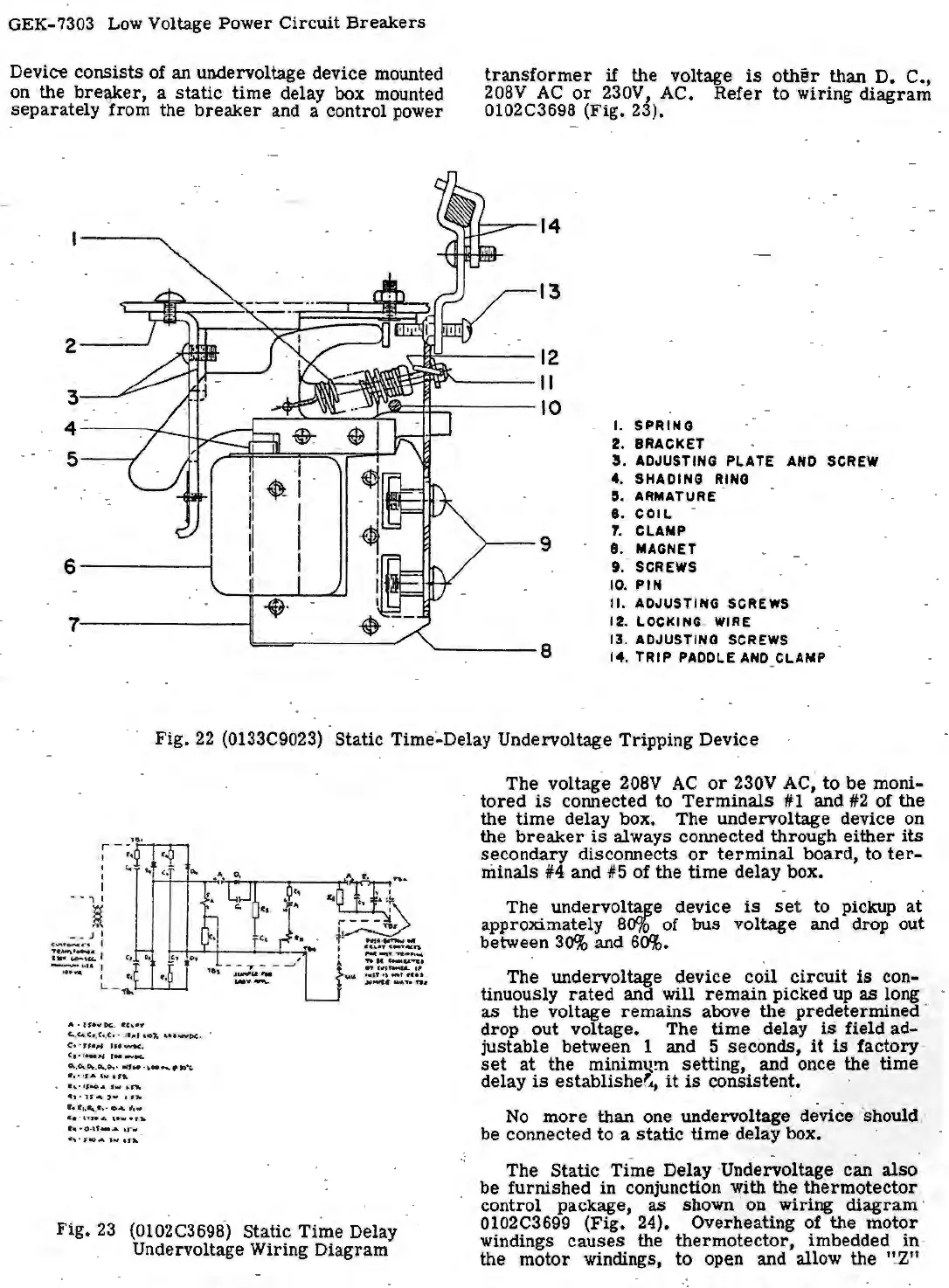
Device consists
of
an undervoltage device mounted
on the
bre¥er,
a
static
time
delay box
mo
unted
sepa
rately from the
breaker
and a control power
2
3
4
5
6
7
transformer
if
the voltage
is
other
than
D.
C.,
208V
AC
or
230V, AC.
Refer
to
wiring
diagram
0102C3698 (Fig. 23).
14
13
12
II
10
I.
SPRING
2.
BRACl<ET
3 . ADJUSTING
PLATE
ANO
SCREW
<t.
SHADING
RING
5. ARMATURE
I .
COIL
.
7.
CLAMP
9
8 . MAGNET
9. · SCREWS
10.
PIN
II.
ADJUSTING
SCREWS
12. LOCKING.
WIRE
13. ADJUST
l~
G SCREWS
8
14.
TRIP
PADDLE
ANO
CLAMP
Fig.
22
(0133C9023) Static Time·-Delay Undervoltage Tripping Device
. • l I
i
- • J I
c
""'
"°"'
•'" I
:~-:.1
--·
·
••1
..
.
.._
I
'•
t,
L _
ff..__.__,__.
A • t t • Y.
k.
•C..•'t'
c.
.
c...
c •• c
._
c
•.
.J
•.-1 ,
..
"
'-
•
•"""'P<
· ·
C,
·
ff
e
,4
JU-.c
.
c, . .
...
.,
,
..
_""
0.,0-..
Pr.
.
o..
.
...
.
..
,
...
-.
........
,
•
..
. ,
...
,.,
.,
....
-
."
.,,..
...
'""
t.t"lti,.
.,. ,,
...
,..,
. ,
,.
,
..
..
.. , •
••
04
"'
·
Ca
•U
toA
l • w
•flt
....
.
o.,,
.-
...
\
r-
~ ·
St0A
\-.,
• f
lrt.
Fig.
23
(0102C3698) Static
Time
Delay
Undervoltage Wiring Diagram
The
voltage 208V
AC
or
230V
AC~
to
be
moni-
tored
is
connected to
Terminals
#1 and
#2
of the
the
time
de
lay
box. The undervoltage device on
the
breaker
is
always connected through
either
its
secondary disconnects
or
terminal
board, to
ter-
mi
nals
#4
and #5 of the
time
delay box •
The
undervolt~e
device
is
set
to pickup
at
approximately
Soto
of
bus
voltage and drop out
between
30%
and
60%.
·
The u.ndervoltage device coil
circuit
is
con-
tinuously
rated
and will
remain
picked up
as
long
as
the voltage
remains
above the predetermined ·
drop
out
voltage. The
time
delay
is
field ad-
justable between 1 and 5 seconds,
it
is
factory·
set
at
the mini
m"Qm
setting; and one~ the
time
delay
is
establisher.,
it
is
con
sistent
•.
No
more
than
one u.ndervoltage device ·should:
be
co
nnect
ed
to a
static
time
delay box.
The S
tatic
Time Delay ·Undervoltage can
also
be furnished in conjunction with the
thermotector
. control package,
as
sh
own · on wiring
diagram
·
0102C3699 (Fig. 24). Overheating of the
motor
windings
causes
the
thermotector,
imbedded
in
·
the
motor
windings,
to
open and allow the
'!2"
 Loading...


