relay
of the "
control
box
to
instantaneously
trip
the
breaker
through .a
normally
closed
"Z"
contact
in
series
with the undervoltage device mounted
on the
breaker.
r--'T-~-.
I
I
I
--,
J
~:
_Ji
c
.,,,-u)
I
~~
"'-:;:~II
L_
.,,.,.,,....._.......,
A•
llflfll(.
•UAr
C,J!.,,(I.Cc,CJ•lf-''•
'
,
..
,,,,,
..
11<
C1•
IH,1
IIHWK
,,
•
..,,...,t
,,,t,(!f(/1(
4.,"1.4.lt·
,,,,,,.
'6t
...... • )
••
(.
.(; •
/JA
Jt,/flj,
,t,•1H!f•tw•JI
.t
1
,71A
$t,1US
~,
•
tJS.A
JrOVt'U,
..
b •
O•IM
1'W
At
•
,_.,,,.,.,
t
J~
4',C,•#A
lhl.
.
,.
,.,_,.,"'-Ar~
)SN,,,_
T•
1.-t~,-,.N<,-.
X•
..
_,.,.
Jllf1U"Pb
,•
)fl
Jlc..
I• 11v11c Kl.&Af
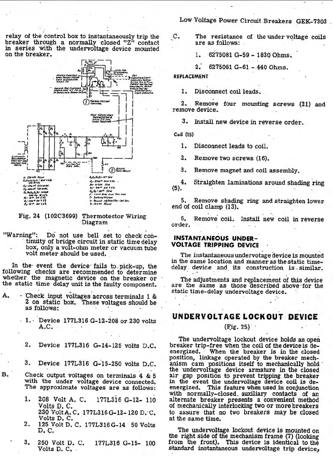
Fig.
24 (102C3699)
Thermotector
Wiring
· ·Diagram
-
"Warning":
Do
not
use
bell
set
to
check con-
. tinuity
of
bridge
circuit
in
static
time delay
box, only a volt-ohm
meter
or
vacuum tube
volt
meter
should be used • .
In
the· event the device·
fails
to
_ pick-up, the
following checks
are
recommended
to
· determine
whether the magnetic device on the
breaker
or
the
static
time
delay unit
is
the faulty component.
A.
- ·
check
input vo1tag·
es
·
across
terminals
1 &
2 on
static
box. These voltages should be
B.
as
follows: ·
1.
- Device 177L316 G~12-208
or
230 volts
A.c
• .
2.
Device 177L316 G-14-125 volts D.C.
3. Device 177L316
G-
-15-250 volts D.C.
Check output voltages on
terminals
4 & 5
with
the
under
voltage device connected.
The
approximate voltages
are
as
follows:
1.
208 Volt A. C.. 177L316 G-12-
110
Volts D. C.
230VoltA.C.
177L316G-12-120D.·C.
Volts D. C.
2. 125 Volt D. C. 177L316 G-14
50
Volts
D.
C.
3.
250 Volt D. C. 177L316 G-15-
100
Volts D. C • .
Low Voltage
Power
Circuit
Breakers
GEK-7303
.. c.
The
resistance
of the under voltage coils
are
as
follows: . ·
1.
6275081 G-59 - 1830 Ohms.
2:
6275081 G-61 -.440 Ohms.
REPLACEMENT
1. Disconnect coil
leads.
2. Remove four mounting
screws
(21) and
remove device.
3. Install new device in
reverse
order.
Coil
(ls)
1.
Disconnect leads to coil.
..
2. Remove two
screws
(16).
3.
Re~ove
magnet and coil
assembly.
4.
Straighten laminations around shading
ring
·(5).
· 5. Remove shading ring and
straig
hten lower
end of coil _clamp (13). .
6. ·Remove· coil. Install new
coil
in
reverse
order.
· ·
-
· INSTANTANEOUS
UNDER-
VOLTAGE TRIPPING
DEVICE
The instantaneous undervotage device
is
mounted
in the
same
location and manner
as
the
static
time-
delay
_.
d~vice . and.
its
construction
is
-
similar.
. .
The adjustments and re_place~ent of
this
device
are
the
same
as
those described above-
for
the
static
time-delay undervoltage device.
UNDERVOLTAGE
LOCKOUT
DEVICE
(~ig.
25)
. ·
The undervoltage lockout device holds
an open
breaker
trip-free
when the coil of the device
is
de-
energized. · When the
breaker
is
in
the closed
position, ~inkage operated by the
breaker
mech-
anism
cam
positions -itself to mechanically hold ·
the undervoltage device armature
in
the closed
air
gap position to prevent tripping the
breaker
in the event the undervoltage device
coil
is
cie-
energized. This feature
when
used in conjunction
with normally-closed. aux:Uiary contacts of
an
alternate
breaker
presents a convenient method·
of mechanically interlocking two
or
more
breakers
to
assure
that
no
two
breakers may
be
closed
at
the
same
time.
The undervoltage lockout device
is
mounted on
the right side of the mechanism
frame
(7) (looking
from the front). This device
is
identical
to
the
standard instantaneous
unde~oltage
trip
device,
 Loading...


