LOW-VOLTAGE POWER
CIRCU~T
BREAKERS
-·
TYPES
. AK•SO,
AK-100
;
AKF-2C,
AKF-
2D,
AKF-2E
OPERATION
INTRODUCTION
.
The
instructions
contained
herein
are
intended to
aid
in
the
maintenance and
repair
of
basic
breakers
and
accessories
for
AK-50-75
-1
00 Low Voltage
Power
Circuit
Breakers.
·
The
basic
AK_.50,
AK-75
and
· AK- 100
breaker
designs
have
been
expanded
to
include
special
designs
for
specific
applications.
These
design
extensions
have
caused
variations
in
the nomen-
clature
including
the
following:
AK-2-50, AK-2- 75
or
AK-2- 100 -
Basic
standard
design
of
breaker
for
stationary
mounting
or
for
drawout
use
in
AKD type
equipment.
AK-2A- 50, AK-2A-75, · AK-2A-100 - The
A
indicates
it
.has_mounting.
features
for
AKD-5 type equipment.
AK-2-50S, AK-2-75S, AK-2-lOOS -
The
S
indicates
breaker
is
equipped with a quick-
close
mechanism
· which
provides
closing
times
of
approximately 5
cycles
(.08 seconds)
..
..
AKU-2-50- -
The
u.
indicates
an
internal
fuse
breaker
combination:
AKF-2C, AKF-2D, AKF-2E . - Are
fie
ld
switches
for
use
in
.controlling
shunffields
of
synchronous
m~tQ~s and
generators.
.
AK
-2-50H -
.The
H Indicates the inter-
.
rupting
rating
has
-
been
increased
to the
75,000
amp
.
class.
. · , _ ·
-
AK
- 2- 50C,-
AK~2
-7
5C-
:..
The C indicates
the
interrupting
rating
has
been
increased
to
the
rno,ooo
amp.
class
. .
AKT-2- 50 -
The
· T
indicates
incr~ased. · ·
continuous
rating
of 2000
amps.
AK-3-50,
AK
-
3-75,
AK-3-100 - The 3
indicates
the
breaker
ls
equippe!i with the
Power
Sensor
OVercurrent
Trip
Device.
AK-2-
50X
- -
The
x·
indicates
the
-
breaker
has
very
special
features
or
it
"includes_ ·
two
or
more
.
of
the
design
extensions
previously
described.
- .-
When contacting .
the
factory'
it
is
important
to
furnish
the
complete
nameplate
· information.
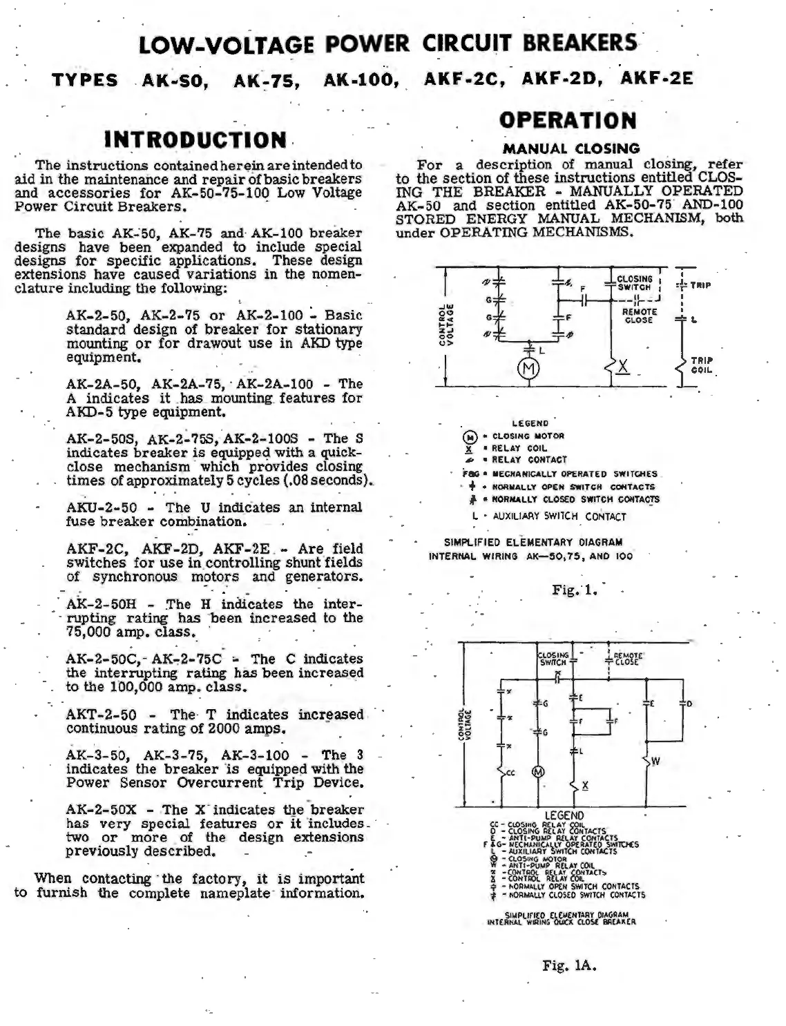
MANUAL
CLOSING
For
a
description
of manual closing,
refer
to
the
section
of
these
instructions
entitled
CLOS
-
ING
THE BREAKER -
MANUALLY
OPERATED
AK-50 and
section
entitled AK-50-75" AND-100
STORED ENERGY
MANUAL
MECHANISM,
both
under
OPERA TING
MECHANISMS.
-'"'
o<:>
a:<(
1-1-
%-'
oo
u>
4'
G
G
,fl
LE
GEND
® •
CLOSING
MOTOR
~
• RELAY
COIL
,1,
• RELAY CONTACT
CLOSING
1
SWITCH
1
--
:
:-~J
REMOTE
CLOSE
.x
.
F&G
• MECHANICALLY
OPfRATED
SWITQIES
.
· + •
NOR
MALLY OPEN SWITCH CONTACTS
I • NORMALLY CLOSED SWITCH
COffTAC_!S
L •
AUXILIAAY
SWITCH
CONTACT
SIMPLIFIED ELEMENTARY
DIAGRAM
INTERNAL WIRING
AK_:50,
75,
AND
100
·
Fig;l.
lOSING
-
1
l'l£
MOTE
"
.r
r
SWITCH
I T ' l
OSE
I • I
G
h;
E
G
"
l
LEGEND
~C
:
~'fc,~l'i,\
ii
t~~
fo~lTACTS
( -
ANTI-PUMP
A£lAT
C<J,ITACTS
r
tG:
~~/r,:ti~~~~Wc\O.,l~lt>f:S
j :
~~~~1s?ct•r
C
Oi
l
~
=~'l::.W&
i~'i.1.~
~TACT:,
<j,
-
t.ORMAllT
OptN
SWITCH
CONTACTS
'f'
-
NORMAU.T
ClOS(O
SWITCH
CONTACTS
INT(~l~.lf
1
~GC~fi~nt~~~U:icR
Fig.
lA.
w
-,--
I
:~
TR
IP
I
I
'
[.
..
OIL .
1
0
 Loading...


