 Loading...
Do you have a question about the GE LOGIQ C9 Series and is the answer not in the manual?
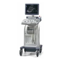
| Power Requirements | 100-240 VAC, 50/60 Hz |
|---|---|
| Applications | Vascular |
| Probe Ports | 4 |
| Operating Modes | B-mode, M-mode, Color Doppler, Power Doppler |
| Transducer Types | Convex, Linear, Phased Array, Volume |
| Connectivity | DICOM, USB, Ethernet |
| Operating System | Windows-based |
Explains the availability of the manual in multiple languages.
Provides an overview of the chapter's contents and structure.
Details the structure and content of the entire service manual.
Lists the specific LOGIQ C9 Series models this manual applies to.
Explains conventions, symbols, and terms used throughout the document.
References product labels and icons used for identification.
Provides information on the location of product labels on the system.
Outlines essential safety precautions for operating and servicing the system.
Highlights warnings for procedures that may pose risks.
Details the procedures for energy control and power lockout.
Provides guidelines for safely returning probes and repair parts.
Explains Electromagnetic Compatibility, Interference, and Discharge prevention.
Provides contact information and support resources for assistance.
Introduces the chapter's objectives and content structure.
Details the environmental and operational requirements for the system.
Outlines temperature, humidity, and pressure parameters for operation and storage.
Specifies the cooling requirements for the ultrasound system.
Discusses lighting needs for installation, updates, and patient comfort.
Details power and electrical specifications necessary for system setup.
Specifies requirements for stable power supply and voltage variations.
Addresses Electromagnetic Interference and its potential sources.
Provides guidelines and rules for preventing or reducing EMI.
Outlines environmental conditions for probe operation, storage, and transport.
Estimates the time and personnel needed for site preparation.
Lists the facility requirements for system installation.
Outlines the purchaser's obligations for site preparation.
Details essential facility requirements like power outlets and door openings.
Lists optional but beneficial features for the installation site.
Offers a suggested layout for a minimal setup space.
Provides a recommended floor plan for optimal system placement.
Illustrates a room layout with the system and EchoPAC PC.
Details requirements for connecting the system to a network.
Specifies requirements for configuring DICOM network connections.
Discusses environmental hazards and patient vicinity safety standards.
Introduces the chapter's objectives and content structure.
Provides important reminders and warnings before system setup.
Guides the process of receiving and unpacking the ultrasound system.
Outlines steps to prepare for system setup, including verification.
Details the final steps to complete the system installation and configuration.
Explains how to configure the LOGIQ C9 Series system settings.
Describes how to install and configure system peripherals.
Covers documentation and paperwork required after system setup completion.
Introduces the chapter's focus on system checks and procedures.
Covers common procedures for system operation and basic tasks.
Instructions for adjusting the LCD monitor's position.
Details the process for logging into the system with administrative privileges.
Explains the use of the service key for diagnostics and maintenance.
Guides on how to exit the application software to the Windows desktop.
Provides instructions on using and managing removable media.
Covers procedures for backing up and restoring system presets.
Instructions for managing presets using InSite ExC.
Step-by-step guide for cleaning the system's trackball.
Outlines procedures for verifying system functionality.
Describes the basic controls and components of the operator panel.
Details checks for probes and their connection ports.
Covers functional checks for system peripherals like printers and pedals.
Explains power supply testing and adjustment procedures.
Provides a checklist for application turnover to the customer.
Information on maintaining a log of site visits and service actions.
Introduces the chapter's focus on system components and their functions.
Explains system architecture through block diagrams and theoretical concepts.
Illustrates the software architecture and its modules.
Details the system's power distribution and AC power components.
Describes the common software platform for service operations.
Introduces the chapter on system adjustments and error testing.
Provides instructions for adjusting LCD monitor settings and factory reset.
Covers touch panel resolution and calibration procedures.
Refers to user manual for LCD panel adjustments.
Introduces the chapter on system diagnostics and troubleshooting tools.
Explains how to collect system information and logs for analysis.
Details procedures for capturing screen images for presentations or documentation.
Guides on configuring the system's network settings for connectivity.
Introduces the chapter on replacing system modules and subsystems.
Provides critical warnings and safety information for replacement procedures.
Covers procedures for disassembling and re-assembling system components.
Lists standard and special tools required for system servicing.
Details the components and overview of the system's body assembly.
Provides instructions for cleaning the system's air filters.
Step-by-step guide for cleaning the trackball roller.
Covers procedures for reinstalling or loading system software.
Instructions for verifying the installed software version.
Guides on reloading the correct preset region after software loading.
Explains how to check if installed options are activated and working.
Verifies if the system correctly recognizes connected probes.
Instructions for reinstalling DICOM devices.
Procedure for calibrating the touch panel if it malfunctions.
Introduces the chapter listing available renewal parts for the system.
Provides a list of abbreviations used in the renewal parts section.
Lists parts categorized by type, including power packs and console assemblies.
Introduces the chapter on system care and maintenance procedures.
Lists critical warnings related to system maintenance and safety.
Explains the importance of maintenance and quality assurance.
Outlines the recommended schedule for system maintenance tasks.
Lists the standard and special tools required for system servicing.
Details preliminary and functional checks for system maintenance.
Covers procedures for probe care, cleaning, and maintenance.
Outlines electrical safety testing procedures and standards.
Specifies acceptable limits for chassis and probe leakage currents.
Guides on testing electrical outlet wiring and grounding.
Details the procedure for checking the system's grounding continuity.
Explains how to perform chassis leakage current testing.
Covers the procedure for testing probe leakage current.
Provides troubleshooting steps for excessive leakage current issues.
Details ultrasound inspection forms and functional/electrical safety checks.
Provides a log template for recording electrical safety test results.